- Catalogs
- ZIEHL-ABEGG
- R-DK...KT(G)
- Products
- Catalogs
- News & Trends
- Exhibitions
R-DK...KT(G)
1 /2Pages

R-DK...KT(G)
1 /2Pages
Catalog excerpts

TIL03_18 (27.11.07) Subject to technical modifications! 9. 9.3.2-GB Transformer based controller for 3~ motors 5-step controller inclusive integral thermistor releasing unit Type: R-DK...KT(G) Examples of applications for controlling 3~ fans in 5-steps Manual 5-step speed change-over of one or more 3~ fans e. g. in: heat exchangers (as warm-air heaters), hoods, ventilation of rooms. An integral thermistor releasing unit type U-EK230E with ATEX-approval can be used for the temperature monitoring of motors in explosion protected range. Six thermistors (DIN 44081 or DIN 44082) can be connected in series. According to the type of motor at least two or three single sensors are installed. Fans used in explosion protected range must have three single sensors. That means at most two motors of this type can be connected. The device includes potential-free and 230 V power on contacts for the connection of damper control motors or gas valves (hoods application) (see on back). Equipment Enclosed version IP21 / 54 Transformer based controllers for voltage controllable 3~ fans • 5-step switch for manual speed control • Remote control (ON/OFF) via potential-free contact (terminals „RT”-„RT”). • Motor protection using thermistor connection (terminals „T1"-„T2"). If one of the thermistor is released, the unit switches off and not on again. Restart after cooling the drive unit by switch-off and after that switch on the mains voltage or by step-switch („reset"). • A power on lamp is integrated. • Automatic switch on after power failure. • Additional power on contact - Potential-free changer - 230 V switched and constant voltage Technical data - Line voltage 3~ 400 V, 50/60 Hz - Output voltage 95 V - 145 V - 190 V - 240 V - 400 V - Max. load of the power on contacts · Potential-free changer (terminals 1, 2, 3) 250 V AC / 2 A · 230 V switched and constant voltage max. 1 A (terminals N«, L«, ) - Max. ambient temperature +40° C - Housing top consists of plastic, colour light grey, bottom aluminium die casting Type Part-No. Rated current Max. line fuse Max. heat dissipation approx. Protection class Weight R-DK3KTG 302567 3 A 6 A 60 W IP54 13.0 kg R-DK4KT 302568 4 A 8 A 75 W IP21 13.0 kg R-DK5.2KTG 302569 5.2 A 13 A 80 W IP54 18.5 kg R-DK7KT 302570 7 A 16 A 110 W IP21 18.5 kg Dimension sheet [mm] Connection diagram R-DK...KT(G) N L1 L2 L3 PE N L1L2L3 Netz / Line / Secteur Nätanslutning 3 ~ 400 V 50/60 Hz 12 11 14 RT U V W 0 1 SR171K13 27.11.2007 N L L 230 V AC Kontaktbelastung Contact rating Pouvoir de coupure Kontaktbelastning RT 1* Wenn Funktion nicht benötigt wird, Klemmen brücken 1* Si la fonction n’est pas utile, les bornes doivent être reliées If function is not needed, terminals must be bridged Om funktionen inte används, måste plintarna byglas 1* Aus / Ein Off / On Arrêt / Marche Av / På 250 V AC max. 2 A 230 V AC max. 1 A T2 T1 M 3 ~ TP TP 3 ~ Motor mit eingebauten Temperaturfühlern with internal thermistors avec thermistances intégrés med utdragen termistorer U V W PE Y/ Ziehl-Abegg AG Heinz-Ziehl-Straße D-74653 Künzelsau Tel.: +49 (0) 7940 16-0 Fax: +49 (0) 7940 16-504 [email protected] http://www.ziehl-abegg.de L
Open the catalog to page 1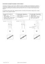
TIL03_18 (27.11.07) Subject to technical modifications! Connection example for damper control motors Connection of damper control motors (different models) is possible via the potential-free contacts or via the 230 V contacts of the power on relay. This relay rises, if the device is activated and the fan is running. By switching off via remote control (terminals „RT”-„RT“) or in case of motor fault the relay falls off. For damper control motors with „single-wire-control” connection with constant voltage (also in switch position „0”) for „damper CLOSE”. For motors with „2-wire-control” - damper...
Open the catalog to page 2All ZIEHL-ABEGG catalogs and technical brochures
 Fans for transformer cooling
260 Pages
 Fans for railroad engineering
334 Pages
 Axial fans main catalogue_2016
544 Pages
 Fans for heat pumps
4 Pages
 ECblue high-efficency motors
14 Pages
 FE2owlet
4 Pages
 ZAwheel
12 Pages
 ZAdyn 4c
4 Pages
 EVAC 3
8 Pages
 MAXvent owlet
10 Pages
 Product range
4 Pages
 Axial Fans Main Catalogue FE2owlet
144 Pages
 Drive technology
112 Pages
 Flyer Fans for wind turbines
5 Pages
 Flyer Cpro ZAmid
4 Pages
 ECblue brochure
20 Pages
 COMPLETE PROGRAMME
24 Pages


Archived catalogs
 FE2owlet-50Hz - part 2 - FN040
11 Pages
 DL2.5 Controllers
38 Pages
 FC100, FC125
38 Pages
 A01 60 Hz North America FB-Series
24 Pages
 A01 60 Hz North America FE-Series
30 Pages
 R-D-1...7
1 Page
 RASE9G
1 Page
 RAE-2/4/7G
1 Page
 R-E1.5...14G
1 Page


- Electromotor
- DC electromotor
- Synchronous motor
- Alternating current motor
- Multipole motor
- Automation software solution
- Asynchronous motor
- Analysis software solution
- EC motor
- Three-phase motor
- Real-time software
- Cloud-based software
- Radial fan
- Control software
- Propeller fan
- Air circulation fan
- 4-pole motor
- Industrial fan
- High-efficiency electromotor
- IP55 motor