Modules - Modules, IGBT - DC Collector Current 100 A and above
1 /5Pages

Modules - Modules, IGBT - DC Collector Current 100 A and above
1 /5Pages
Catalog excerpts

Document Number: 94362 For technical questions, contact: [email protected] www.vishay.com Revision: 03-May-10 1 "Half-Bridge" IGBT INT-A-PAK (Standard Speed IGBT), 200 A GA200HS60S1PbF Vishay High Power Products FEATURES • Generation 4 IGBT technology • Standard: Optimized for hard switching speed DC to 1 kHz • Very low conduction losses • Industry standard package • UL approved file E78996 • Compliant to RoHS directive 2002/95/EC • Designed and qualified for industrial level BENEFITS • Increased operating efficiency • Direct mounting to heatsink • Performance optimized as output inverter stage for TIG welding machines PRODUCT SUMMARY VCES 600 V IC DC 480 A VCE(on) at 200 A, 25 °C 1.13 V INT-A-PAK ABSOLUTE MAXIMUM RATINGS PARAMETER SYMBOL TEST CONDITIONS MAX. UNITS Collector to emitter voltage VCES 600 V Continuous collector current IC TC = 25 °C 480 A TC = 116 °C 200 Pulsed collector current ICM 800 Peak switching current ILM 800 Gate to emitter voltage VGE ± 20 V RMS isolation voltage VISOL Any terminal to case, t = 1 minute 2500 Maximum power dissipation PD TC = 25 °C 830 W TC = 85 °C 430 ELECTRICAL SPECIFICATIONS (TJ = 25 °C unless otherwise specified) PARAMETER SYMBOL TEST CONDITIONS MIN. TYP. MAX. UNITS Collector to emitter breakdown voltage VBR(CES) VGE = 0 V, IC = 1 mA 600 - - Collector to emitter voltage VCE(on) V VGE = 15 V, IC = 200 A - 1.13 1.21 VGE = 15 V, IC = 200 A, TJ = 125 °C - 1.08 1.18 Gate threshold voltage VGE(th) IC = 0.25 mA 3 4.5 6 Collector to emitter leakage current ICES VGE = 0 V, VCE = 600 V - 0.025 1 mA VGE = 0 V, VCE = 600 V, TJ = 125 °C - - 10 Gate to emitter leakage current IGES VGE = ± 20 V - - ± 250 nA
Open the catalog to page 1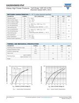
www.vishay.com For technical questions, contact: [email protected] Document Number: 94362 2 Revision: 03-May-10 GA200HS60S1PbF Vishay High Power Products "Half-Bridge" IGBT INT-A-PAK (Standard Speed IGBT), 200 A Fig. 1 - Typical Output Characteristics Fig. 2 - Typical Transfer Characteristics SWITCHING CHARACTERISTICS (TJ = 25 °C unless otherwise specified) PARAMETER SYMBOL TEST CONDITIONS MIN. TYP. MAX. UNITS Total gate charge Qg IC = 200 A VCC = 400 V VGE = 15 V - 1600 1700 Gate to emitter charge Qge - 260 340 nC Gate to collector charge Qgc - 580 670 Turn-on switching loss Eon IC = 200...
Open the catalog to page 2
Document Number: 94362 For technical questions, contact: [email protected] www.vishay.com Revision: 03-May-10 3 GA200HS60S1PbF "Half-Bridge" IGBT INT-A-PAK (Standard Speed IGBT), 200 A Vishay High Power Products Fig. 3 - Case Temperature vs. Maximum Collector Current Fig. 4 - Typical Collector to Emitter Voltage vs. Junction Temperature Fig. 5 - Typical Gate Charge vs. Gate to Emitter Voltage Fig. 6 - Typical Switching Losses vs. Gate Resistance Fig. 7 - Typical Switching Losses vs. Collector to Emitter Current 160 140 120 100 100 200 300 400 500 80 60 40 20 0 0 TC - Case Temperature (°C)...
Open the catalog to page 3
www.vishay.com For technical questions, contact: [email protected] Document Number: 94362 4 Revision: 03-May-10 GA200HS60S1PbF Vishay High Power Products "Half-Bridge" IGBT INT-A-PAK (Standard Speed IGBT), 200 A ORDERING INFORMATION TABLE LINKS TO RELATED DOCUMENTS Dimensions www.vishay.com/doc?95067 1 - Essential part number IGBT modules 2 - Current rating (200 = 200 A) 3 - Circuit configuration (H = Half bridge without f/w diode) 4 - INT-A-PAK 5 - Voltage code (60 = 600 V) 6 - Speed/type (S = Standard speed IGBT) 8 - PbF = Lead (Pb)-free 7 - Assy location Italy Device code 1 2 3 4 5 6 7...
Open the catalog to page 4
Document Number: 91000 www.vishay.com Revision: 11-Mar-11 1 Disclaimer Legal Disclaimer Notice Vishay ALL PRODUCT, PRODUCT SPECIFICATIONS AND DATA ARE SUBJECT TO CHANGE WITHOUT NOTICE TO IMPROVE RELIABILITY, FUNCTION OR DESIGN OR OTHERWISE. Vishay Intertechnology, Inc., its affiliates, agents, and employees, and all persons acting on its or their behalf (collectively, “Vishay”), disclaim any and all liability for any errors, inaccuracies or incompleteness contained in any datasheet or in any other disclosure relating to any product. Vishay makes no warranty, representation or guarantee regarding...
Open the catalog to page 5All VISHAY catalogs and technical brochures
 VS-E5TH1506THN3
8 Pages
 VS-E5TX1506THN3
8 Pages
 VS-E5TH3006THN3
8 Pages
 VS-E5TX3006THN3
8 Pages
 VS-E5PH3006LHN3
6 Pages
 VS-E5PX3006LHN3
6 Pages
 VS-E5PH6006LHN3
6 Pages
 VS-E5PX6006LHN3
6 Pages
 VS-E5PH7506LHN3
6 Pages
 VS-E5PX7506LHN3
6 Pages
 VCNL36825T
16 Pages
 VS-E5TH1506-M3
7 Pages
 VS-E5TX1506-M3
7 Pages
 VS-E5TH3006-M3
7 Pages
 VS-E5TX3006-M3
7 Pages
 VS-E5PH3006L-N3
8 Pages
 VS-E5PX3006L-N3
7 Pages
 VS-E5PH6006L-N3
7 Pages
 VS-E5PX6006L-N3
7 Pages
 VS-E5PH7506L-N3
7 Pages
 VS-E5PX7506L-N3
7 Pages
 VS-C04ET07T-M3
5 Pages
 VS-C06ET07T-M3
5 Pages
 VS-C08ET07T-M3
5 Pages
 VS-C10ET07T-M3
5 Pages
 VS-C12ET07T-M3
5 Pages
 VS-C16CP07L-M3
5 Pages
 VS-C16ET07T-M3
5 Pages
 VS-C20CP07L-M3
5 Pages
 VS-C20ET07T-M3
5 Pages
 VS-C40CP07L-M3
5 Pages
 P11H
P11H7 Pages
 IHTH-1500MZ-5A
4 Pages
 IHTH-1500TZ-5A
4 Pages
 MFU AT SERIES
8 Pages
 T24
T247 Pages
 CRHA
CRHA4 Pages
 IHXL-1500VZ-5A
5 Pages
 Power Modules
32 Pages
 Bare Die
29 Pages
 TMBS® Rectifiers
2 Pages
 XOSM-531 OSCILLATORS
3 Pages
 IHLP2525EZ-01 INDUCTORS
4 Pages
 HYBRIDS & SUBSTRATES HP - MT
2 Pages
 Fuses HCTF CP Series
5 Pages
 XT49S CRYSTALS
3 Pages
 VOM1271 SOLID-STATE RELAYS
7 Pages
 Si5904DC MOSFETS
9 Pages
 Chip Antenna
6 Pages
 2381 691 90001/HUMIDITY-SENS-E
2 Pages
 Inductors - Power Inductors
2 Pages
 Capacitors - Ceramic
7 Pages
 Capacitors - Radial
5 Pages


Archived catalogs
 RC Thermal Model for 2N7002K
3 Pages
 MLCC Product Road Map
4 Pages


- Connector
- Display module
- Proximity switch
- Rectangular connector
- Switching relay
- Capacitor
- LED display panel
- Position transducer
- Inductive proximity sensor
- Transceiver module
- Linear position transmitter
- Electronic display panel
- Radio antenna
- Analog position transducer
- Medical equipment display
- No-contact position sensor
- SMT connector
- Potentiometer
- Omnidirectional antenna