Chip Antenna
1 /6Pages

Chip Antenna
1 /6Pages
Catalog excerpts
VJ 3505 UHF Chip Antenna for Mobile Devices www.vishay.com For technical questions, contact: [email protected] Document Number: 45158 20 Revision: 26-Aug-10 VJ 3505 Vishay Vitramon The company’s products are covered by one or more of the following: WO2008250262 (A1), US2008303720 (A1), US2008305750 (A1), WO2008154173 (A1). Other patents pending. DESCRIPTION The VJ 3505 multi-layer ceramic chip antenna is a small form-factor, high-performance, chip-antenna designed for TV reception in mobile devices in the UHF band. It allows mobile TV device manufacturers to design high quality products that do not bear the penalty of a large external antenna. Utilizing Vishay's unique materials and manufacturing technologies, this product complies with the MBRAI standard while maintaining a small outline. Focusing on consumer applications, the antenna is designed to be assembled onto a PC board in the standard reflow process. Target customers of the VJ 3505 are mobile phone makers, portable multimedia device makers, notebook OEMs and ODMs, and accessory card OEMs and ODMs. FEATURES • Small outline (35 mm x 5 mm x 1.2 mm) • Omni-directional, linear polarization • Complies with MBRAI standard • Complete UHF band coverage (470 MHz to 860 MHz) up to 1.1 GHz • Requires a tuning circuit and ground plane for optimal performance • Standard SMT assembly • 50 Ù unbalanced interface • Operating temperature range (- 40 °C to + 85 °C) • Reference design and evaluation boards available upon request • Compliant to RoHS directive 2002/95/EC APPLICATIONS • Mobile UHF TV receivers including DVB-T, DVB-H, ISDB-T, CMMB, ATSC, and MediaFLO devices ANTENNA PERFORMANCE Peak gain and efficiency The antenna radiation characteristics are influenced by several factors including ground plane dimensions and impedance matching network. The antenna parameters presented hereafter were simulated according to the ground plane configuration suggested by the VJ 3505 evaluation board. Figure 1. shows simulated peak gain and radiation efficiency over frequency throughout the UHF band, compared with the MBRAI requirements. Fig. 1 - Peak Gain and Efficiency vs. Frequency VJ 3505 Simulated Antenna Parameters - 12 - 10 - 8 - 6 - 4 - 2 0 2 Frequency (MHz) Radiation Efficiency (dB) 470 520 570 620 670 720 770 820 870 Radiation Efficiency MBRAI Peak Gain
Open the catalog to page 1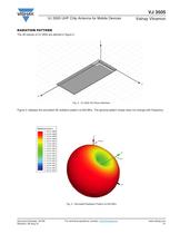
Document Number: 45158 For technical questions, contact: [email protected] www.vishay.com Revision: 26-Aug-10 21 VJ 3505 VJ 3505 UHF Chip Antenna for Mobile Devices Vishay Vitramon RADIATION PATTERN The 3D planes of VJ 3505 are defined in figure 2. Fig. 2 - VJ 3505 3D Plane Definition Figure 3. displays the simulated 3D radiation pattern at 550 MHz. The general pattern shape does not change with frequency. Fig. 3 - Simulated Radiation Pattern at 550 MHz X Z Y
Open the catalog to page 2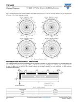
www.vishay.com For technical questions, contact: [email protected] Document Number: 45158 22 Revision: 26-Aug-10 VJ 3505 Vishay Vitramon VJ 3505 UHF Chip Antenna for Mobile Devices Fig. 4 displays the measured radiation patterns of VJ 3505 evaluation board in the YZ plane as defined in Fig. 2. Zero degrees is defined at the Z axis, stepping clockwise. Fig. 4 - Measured Radiation Pattern FOOTPRINT AND MECHANICAL DIMENSIONS The antenna footprint and mechanical dimensions are presented in figure 5. For mechanical support, it is recommended to add one or two drops of heat curing epoxy glue. The glue...
Open the catalog to page 3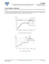
Document Number: 45158 For technical questions, contact: [email protected] www.vishay.com Revision: 26-Aug-10 23 VJ 3505 VJ 3505 UHF Chip Antenna for Mobile Devices Vishay Vitramon VJ 3505 ASSEMBLY GUIDELINES 1. Mounting of antennas on a printed circuit board should be done by reflow soldering. The reflow soldering profiles are shown below. 2. In order to provide the adequate strength between the antenna and the PCB the application of a dot of heat cured epoxy glue in the center of the footprint of the antenna prior to the antenna’s soldering to the board should be done. An example for such glue...
Open the catalog to page 4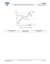
Document Number: 45158 For technical questions, contact: [email protected] www.vishay.com Revision: 26-Aug-10 24 VJ 3505 VJ 3505 UHF Chip Antenna for Mobile Devices Vishay Vitramon Fig. 8 - Soldering IR Reflow with SnAgCu Solder 0 50 100 150 200 250 300 T (°C) Time 60 s to 120 s 30 s to 60 s Max. temperature Min. temperature Sn-Ag-Cu solder paste 60 s to 120 s 60 s to 120 s ORDERING INFORMATION VISHAY MATERIAL PACKAGING QUANTITY VJ 3505 VJ3505M011SXMSRA0 1000 pieces
Open the catalog to page 5
Document Number: 91000 www.vishay.com Revision: 11-Mar-11 1 Disclaimer Legal Disclaimer Notice Vishay ALL PRODUCT, PRODUCT SPECIFICATIONS AND DATA ARE SUBJECT TO CHANGE WITHOUT NOTICE TO IMPROVE RELIABILITY, FUNCTION OR DESIGN OR OTHERWISE. Vishay Intertechnology, Inc., its affiliates, agents, and employees, and all persons acting on its or their behalf (collectively, “Vishay”), disclaim any and all liability for any errors, inaccuracies or incompleteness contained in any datasheet or in any other disclosure relating to any product. Vishay makes no warranty, representation or guarantee regarding...
Open the catalog to page 6All VISHAY catalogs and technical brochures
 VS-E5TH1506THN3
8 Pages
 VS-E5TX1506THN3
8 Pages
 VS-E5TH3006THN3
8 Pages
 VS-E5TX3006THN3
8 Pages
 VS-E5PH3006LHN3
6 Pages
 VS-E5PX3006LHN3
6 Pages
 VS-E5PH6006LHN3
6 Pages
 VS-E5PX6006LHN3
6 Pages
 VS-E5PH7506LHN3
6 Pages
 VS-E5PX7506LHN3
6 Pages
 VCNL36825T
16 Pages
 VS-E5TH1506-M3
7 Pages
 VS-E5TX1506-M3
7 Pages
 VS-E5TH3006-M3
7 Pages
 VS-E5TX3006-M3
7 Pages
 VS-E5PH3006L-N3
8 Pages
 VS-E5PX3006L-N3
7 Pages
 VS-E5PH6006L-N3
7 Pages
 VS-E5PX6006L-N3
7 Pages
 VS-E5PH7506L-N3
7 Pages
 VS-E5PX7506L-N3
7 Pages
 VS-C04ET07T-M3
5 Pages
 VS-C06ET07T-M3
5 Pages
 VS-C08ET07T-M3
5 Pages
 VS-C10ET07T-M3
5 Pages
 VS-C12ET07T-M3
5 Pages
 VS-C16CP07L-M3
5 Pages
 VS-C16ET07T-M3
5 Pages
 VS-C20CP07L-M3
5 Pages
 VS-C20ET07T-M3
5 Pages
 VS-C40CP07L-M3
5 Pages
 P11H
P11H7 Pages
 IHTH-1500MZ-5A
4 Pages
 IHTH-1500TZ-5A
4 Pages
 MFU AT SERIES
8 Pages
 T24
T247 Pages
 CRHA
CRHA4 Pages
 IHXL-1500VZ-5A
5 Pages
 Power Modules
32 Pages
 Bare Die
29 Pages
 TMBS® Rectifiers
2 Pages
 XOSM-531 OSCILLATORS
3 Pages
 IHLP2525EZ-01 INDUCTORS
4 Pages
 HYBRIDS & SUBSTRATES HP - MT
2 Pages
 Fuses HCTF CP Series
5 Pages
 XT49S CRYSTALS
3 Pages
 VOM1271 SOLID-STATE RELAYS
7 Pages
 Si5904DC MOSFETS
9 Pages
 2381 691 90001/HUMIDITY-SENS-E
2 Pages
 Inductors - Power Inductors
2 Pages
 Capacitors - Ceramic
7 Pages
 Capacitors - Radial
5 Pages


Archived catalogs
 RC Thermal Model for 2N7002K
3 Pages
 MLCC Product Road Map
4 Pages


- Connector
- Proximity switch
- Rectangular connector
- Switching relay
- Capacitor
- LED display panel
- Position transducer
- Inductive proximity sensor
- Transceiver module
- Linear position transmitter
- Electronic display panel
- Radio antenna
- Analog position transducer
- Medical equipment display
- No-contact position sensor
- SMT connector
- Diode
- Potentiometer
- Omnidirectional antenna