Capacitors - Ceramic
1 /7Pages

Capacitors - Ceramic
1 /7Pages
Catalog excerpts
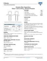
Ceramic Disc Capacitors Class 1 and 2, 50 VDC, General Purpose www.vishay.com For technical questions, contact: [email protected] Document Number: 28510 22 Revision: 04-Jan-10 D Series Vishay BCcomponents Capacitors with 5 mm (0.20") and 2.5 mm (0.10") lead spacing MARKING Marking indicates capacitance value and tolerance in accordance with “EIA 198” OPERATING TEMPERATURE RANGE Class 1, - 55 °C to + 125 °C Class 2, - 30 °C to + 85 °C TEMPERATURE COEFFICIENT Y5R (2C4) - 30 °C TO + 85 °C Class 1, NP0; SL0 Class 2, Y5P; Z5U; Y5V; Z5V SECTIONAL SPECIFICATIONS Class 1, IEC 60 384-8, Class 2, IEC 60 384-9, EIA 198 CLIMATIC CATEGORY Class 1, - 55 °C to + 125 °C Class 2, - 30 °C to + 85 °C FEATURES • Low losses • High stability • High capacitance in small size • Kinked (preferred) or straight leads • Compliant to RoHS directive 2002/95/EC APPLICATIONS • Bypassing • Coupling • Resonant circuit DESIGN The capacitors consist of a ceramic disc both sides of which are silver-plated. Connection leads are made of tinned copper having a diameter of 0.6 mm. The capacitors have inward kinked leads with a spacing of 5 mm (0.20") and straight leads with 2.5 mm (0.10"), lead length from 4 mm to 30 mm. Encapsulation is made of phenolic resin. CAPACITANCE RANGE Class 1, at 1 MHz, 1.2 VRMS; 1.0 pF to 100 pF 1 kHz, 1 VRMS ± 0.2 VRMS for capacitance values higher than 1000 pF Class 2, at 1 kHz, 1 VRMS ± 0.2 VRMS 150 pF to 47 000 pF RATED DC VOLTAGE 50 V DIELECTRIC STRENGTH 250 % of rated voltage INSULATION RESISTANCE AT 500 VDC 10 000 MÙ TOLERANCE ON CAPACITANCE ± 5 %; ± 10 %; ± 20 %; + 80 %/- 20 % DISSIPATION FACTOR Class 1, C 30 pF 20 x (10/C + 0.7) x 10-4 maximum Class 1, C > 30 pF 0.2 % Class 2, 3.0 % Note • The capacitors meet the essential requirements of “IEC 60384-9 and EIA 198”. Unless stated otherwise all electrical values apply at an ambient temperature of 25 °C ± 3 °C, at normal atmospheric conditions QUICK REFERENCE DATA DESCRIPTION CLASS 1 (NP0, SL0) CLASS 2 (Y5P, Z5U, Y5V, Z5V) Voltage (VDC) 50 Min. Capacitance (pF) 1 150 Max. Capacitance (pF) 100 47 000 Mounting Through hole D F Tangent line DR Tangent line D SH F
Open the catalog to page 1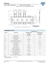
www.vishay.com For technical questions, contact: [email protected] Document Number: 28510 26 Revision: 04-Jan-10 D Series Vishay BCcomponents Ceramic Disc Capacitors Class 1 and 2, 50 VDC, General Purpose Notes (1) Cumulative pitch error: ± 1 mm/20 pitches (2) Obliquity maximum 3° ÄP ÄP D P2 P Äh Äh P1 P0 D0 H1 H0 Direction of unreeling Ø d F W2 W1 t1 W0 W e A Kinked capacitors on tape, lead spacing 5.0 mm (0.2") detail A DIMENSIONS OF TAPE SYMBOL PARAMETER DIMENSIONS (mm) FEED-HOLE PITCH P0 = 12.7 FEED-HOLE PITCH P0 = 15.0 NOMINAL TOLERANCE D Body diameter 11.0 maximum - d Lead diameter 0.6 ± 0.05...
Open the catalog to page 5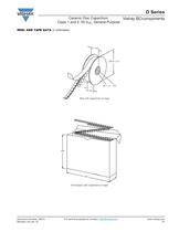
Document Number: 28510 For technical questions, contact: [email protected] www.vishay.com Revision: 04-Jan-10 27 D Series Ceramic Disc Capacitors Class 1 and 2, 50 VDC, General Purpose Vishay BCcomponents REEL AND TAPE DATA in millimeters 28 ± 1.5 355.6 ± 2.0 8.0 45 max. 51 max. Reel with capacitors on tape 290 335 50 Ammopack with capacitors on tape
Open the catalog to page 6
Document Number: 91000 www.vishay.com Revision: 18-Jul-08 1 Disclaimer Legal Disclaimer Notice Vishay All product specifications and data are subject to change without notice. Vishay Intertechnology, Inc., its affiliates, agents, and employees, and all persons acting on its or their behalf (collectively, “Vishay”), disclaim any and all liability for any errors, inaccuracies or incompleteness contained herein or in any other disclosure relating to any product. Vishay disclaims any and all liability arising out of the use or application of any product described herein or of any information provided...
Open the catalog to page 7All VISHAY catalogs and technical brochures
 VS-E5TH1506THN3
8 Pages
 VS-E5TX1506THN3
8 Pages
 VS-E5TH3006THN3
8 Pages
 VS-E5TX3006THN3
8 Pages
 VS-E5PH3006LHN3
6 Pages
 VS-E5PX3006LHN3
6 Pages
 VS-E5PH6006LHN3
6 Pages
 VS-E5PX6006LHN3
6 Pages
 VS-E5PH7506LHN3
6 Pages
 VS-E5PX7506LHN3
6 Pages
 VCNL36825T
16 Pages
 VS-E5TH1506-M3
7 Pages
 VS-E5TX1506-M3
7 Pages
 VS-E5TH3006-M3
7 Pages
 VS-E5TX3006-M3
7 Pages
 VS-E5PH3006L-N3
8 Pages
 VS-E5PX3006L-N3
7 Pages
 VS-E5PH6006L-N3
7 Pages
 VS-E5PX6006L-N3
7 Pages
 VS-E5PH7506L-N3
7 Pages
 VS-E5PX7506L-N3
7 Pages
 VS-C04ET07T-M3
5 Pages
 VS-C06ET07T-M3
5 Pages
 VS-C08ET07T-M3
5 Pages
 VS-C10ET07T-M3
5 Pages
 VS-C12ET07T-M3
5 Pages
 VS-C16CP07L-M3
5 Pages
 VS-C16ET07T-M3
5 Pages
 VS-C20CP07L-M3
5 Pages
 VS-C20ET07T-M3
5 Pages
 VS-C40CP07L-M3
5 Pages
 P11H
P11H7 Pages
 IHTH-1500MZ-5A
4 Pages
 IHTH-1500TZ-5A
4 Pages
 MFU AT SERIES
8 Pages
 T24
T247 Pages
 CRHA
CRHA4 Pages
 IHXL-1500VZ-5A
5 Pages
 Power Modules
32 Pages
 Bare Die
29 Pages
 TMBS® Rectifiers
2 Pages
 XOSM-531 OSCILLATORS
3 Pages
 IHLP2525EZ-01 INDUCTORS
4 Pages
 HYBRIDS & SUBSTRATES HP - MT
2 Pages
 Fuses HCTF CP Series
5 Pages
 XT49S CRYSTALS
3 Pages
 VOM1271 SOLID-STATE RELAYS
7 Pages
 Si5904DC MOSFETS
9 Pages
 Chip Antenna
6 Pages
 2381 691 90001/HUMIDITY-SENS-E
2 Pages
 Inductors - Power Inductors
2 Pages
 Capacitors - Radial
5 Pages


Archived catalogs
 RC Thermal Model for 2N7002K
3 Pages
 MLCC Product Road Map
4 Pages


- Connector
- Display module
- Proximity switch
- Rectangular connector
- Switching relay
- LED display panel
- Position transducer
- Inductive proximity sensor
- Transceiver module
- Linear position transmitter
- Electronic display panel
- Radio antenna
- Analog position transducer
- Medical equipment display
- No-contact position sensor
- SMT connector
- Diode
- Potentiometer
- Omnidirectional antenna