Group: Velmex

Catalog excerpts
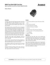
Quick Assembly Two and Three Channel Optical Encoders Data Sheet The HEDS-5500/5540, HEDS-5600/5640, HEDM-5500/5540 and HEDM-5600 are high performance, low cost, two and three channel optical incremental encoders. These encoders emphasize high reliability, high resolution, and easy assembly. • Two channel quadrature output with optional index Each encoder contains a lensed LED source, an integrated circuit with detectors and output circuitry, and a codewheel which rotates between the emitter and detector IC. The outputs of the HEDS-5500/5600 and HEDM-5500/ 5600 are two square waves in quadrature. The HEDS-5540/5640 and HEDM-5540 also have a third channel index output in addition to the two channel quadrature. This index output is a 90 electrical degree, high true index pulse which is generated once for each full rotation of the codewheel. • External mounting ears available The HEDS series utilizes metal codewheels, while the HEDM series utilizes a film codewheel allowing for resolutions to 1024 CPR. The HEDS-5500, 5540, 5600, 5640, and the HEDM-5500, 5540,5600 provide motion detection at a low cost, making them ideal for high volume applications. Typical applications include printers, plotters, tape drives, positioning tables, and automatic handlers. These encoders may be quickly and easily mounted to a motor. For larger diameter motors, the HEDM-5600, and HEDS-5600/5640 feature external mounting ears. The quadrature signals and the index pulse are accessed through five 0.025 inch square pins located on 0.1 inch centers. Standard resolutions between 96 and 1024 counts per revolution are presently available. Consult local Avago sales representatives for other resolutions. pulse • Quick and easy assembly • No signal adjustment required • Low cost • Resolutions up to 1024 counts per revolution • Small size –40°C to 100°C operating temperature • TTL compatible • Single 5 V supply Note: Avago Technologies encoders are not recommended for use in safety critical applications. Eg. ABS braking systems, power steering, life support systems and critical care medical equipment. Please contact sales representative if more clarification is needed. ESD WARNING: NORMAL HANDLING PRECAUTIONS SHOULD BE TAKEN TO AVOID STATIC DISCHARGE.
Open the catalog to page 1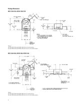
Package Dimensions 1. LEAVE CLEARANCE FOR TURNING MILLIMETERS (INCHES). INDEX PULSE INDEX PULSE 1 LEAVE CLEARANCE FOR TURNING AND REMOVING HEX WRENCH 2 TYPICAL DIMENSIONS IN MILLIMETERS (INCHES).
Open the catalog to page 2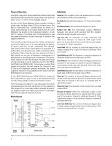
The HEDS-5500/5540, HEDS-5600/5640, HEDM-5500/5540 and HEDM-5600 translate the rotary motion of a shaft into either a two- or a three-channel digital output. Count (N): The number of bar and window pairs or counts per revolution (CPR) of the codewheel. As seen in the block diagram, these encoders contain a single Light Emitting Diode (LED) as its light source. The light is collimated into a parallel beam by means of a single polycarbonate lens located directly over the LED. Opposite the emitter is the integrated detector circuit. This IC consists of multiple sets of photodetectors and the...
Open the catalog to page 3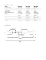
Absolute Maximum Ratings Parameter Output Current per Channel, IOUT Shaft Axial Play Shaft Eccentricity Plus Radial Play
Open the catalog to page 4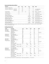
Recommended Operating Conditions Units Notes Temperature HEDS Series Temperature HEDM Series 5500/5600 Supply Voltage Volts Ripple < 100 mVp-p Load Capacitance Count Frequency Shaft Perpendicularity Plus Axial Play (HEDS Series) (±0.010) (in.) from mounting surface Shaft Eccentricity Plus Radial Play (HEDS Series) (0.0015) TIR from mounting surface Shaft Perpendicularity Plus Axial Play (HEDM Series) (±0.007) (in.) from mounting surface Shaft Eccentricity Plus Radial Play(HEDM Series) (0.0015) TIR from mounting surface Note:The module performance is guaranteed to 100 kHz but can operate at...
Open the catalog to page 5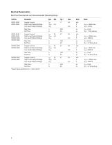
Electrical Characteristics Electrical Characteristic over Recommended Operating Range High Level OutputVoltage VOH 2.4 Low Level Output Voltage VOL Rise Time Fall Time High Level OutputVoltage VOH 2.4 Rise Time Fall Time High Level OutputVoltage VOH 2.4 Rise Time Fall Time High Level OutputVoltage VOH 2.4 Rise Time Fall Time 'Typical values specified atVcc = 5.0Vand 25°C
Open the catalog to page 6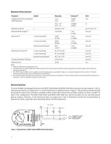
Mechanical Characteristics Codewheel Fits These Standard Shaft Diameters Required Shaft Length [2] external mounting ears external mounting ears Encoder Base Plate Thickness Mounting Screw Size [4] Notes: 1. These are tolerances required of the user. 2. The HEDS-55x5 and 56x5, HEDM-5505, 5605 provide an 8.9 mm (0.35 inch) diameter hole through the housing for longer motor shafts. See Ordering Information. 3. The HEDS-5540 and 5640 must be aligned using the aligning pins as specified in Figure 3, or using the alignment tool as shown in “Encoder Mounting and Assembly”. See also “Mounting...
Open the catalog to page 7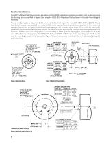
Mounting Considerations The HEDS-5540 and 5640 three channel encoders and the HEDM Series high resolution encoders must be aligned using the aligning pins as specified in Figure 3, or using the HEDS-8910 Alignment Tool as shown in Encoder Mounting and The use of aligning pins or alignment tool is recommended but not required to mount the HEDS-5500and 5600. If these two channel encoders are attached to a motor with the screw sizes and mounting tolerances specified in the mechanical characteristics section without any additional mounting bosses, the encoder output errors will be within the...
Open the catalog to page 8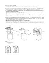
Encoder Mounting and Assembly 1a. For HEDS-5500 and 5600: Mount encoder base plate onto motor. Tighten screws. Go on to step 2. 1b. For HEDS-5540, 5640 and HEDM-5500, 5600, 5540 : Slip alignment tool onto motor shaft. With alignment tool in place, mount encoder baseplate onto motor as shown above. Tighten screws. Remove alignment tool. 1c. It is recommended that adhesive* is applied to the screw-baseplate interface to prevent screw loosening due to effect of high temperature on plastic 2. Snap encoder body onto base plate locking all 4 snaps. 3a. Push the hex wrench into the body of the...
Open the catalog to page 9All VELMEX catalogs and technical brochures
-
 UNISLIDE® TA SYSTEM LAYOUT
1 Pages
-
 Limit Switches
7 Pages
-
 Rotary-incremental-encoder
3 Pages
-
 Velmex Catalog
149 Pages
-
 Linear and Rotary Encoders
5 Pages
-
 XSlide Spec Overview
8 Pages
-
 VRO™ Digital Readout Spec Sheet
10 Pages
-
 Magnetic_Encoder
1 Pages
-
 Inductive_LinearTapeEncoders
15 Pages
-
 PK296B2A-SG36,_StepperMotor
3 Pages
-
 PK296B2A-SG18,_StepperMotor
3 Pages
-
 PK296B2A-SG10,_StepperMotor
3 Pages
-
 PK264-03A,_StepperMotor
2 Pages
-
 PK243A1A-SG18,_StepperMotor
2 Pages
-
 Lead Screw Translation
6 Pages
-
 VXM Full Command Summary
3 Pages
-
 VXM Controller
8 Pages
-
 UniSlide
16 Pages
-
 TA System 7-1-14 Rev C
4 Pages
-
 BiSlide Side Knob
2 Pages
-
 BISlide Catolog
16 Pages


Archived catalogs
-
 VRO Overview
5 Pages


