- Products
- Catalogs
- News & Trends
- Exhibitions
Catalogue Caged Ball LM Guide
1 /23Pages

Catalogue Caged Ball LM Guide
1 /23Pages
Catalog excerpts

General Description General Catalog
Open the catalog to page 1
General Description Selection Flow Chart 1. Setting Conditions Dimensions of machines and systems Space in the guide section Installation direction (horizontal, vertical, slant mount, wall mount, suspended) Magnitude and direction of the working load Stroke length Selecting a Drive Method 2. Selecting a Type Select a type that meets the conditions LM Guide Miniature Guide Slide Pack Ball Spline Linear Bushing 3. Predicting the Service Life Speed Operating frequency (duty cycle) Required service life Kinetic frequency Environment LM Stroke Cross Roller Guide Linear Stage Roller Type etc. Selecting...
Open the catalog to page 2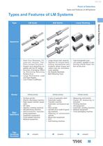
Point of Selection Types and Features of LM Systems Types and Features of LM Systems Type Ball Spline Linear Bushing General Description Major Applications Page introducing the product • Ideal Four Raceway, Circular-Arc Groove, TwoPoint Contact Structure • Superb error-absorbing capability with the DF design • Accuracy Averaging Effect by Absorbing Mounting Surface Error • Large Permissible Load and High Rigidity • Low Friction Coefcient • Large torque load capacity • Interchangeable type • Optimal for torque-trans- • LM system capable of permitting mechanisms and forming infinite linear molocations...
Open the catalog to page 3
Precision Linear Pack Cross Roller Guide • Long service life, high rigid• Capable of performing ro- • Ultra-thin lightweight type tary motion, straight motion • Reduced design and asity and complex motion sembly costs • Easy clearance adjustment type • Capable of performing rolling motion with an extremely small friction coefcient • Low cost Major Applications Page introducing the product Finite stroke Innite stroke Finite stroke • Press die setting • Ink roll unit of printing machine • Optical measuring instrument • Spindle • Solenoid valve guide • Press post guide • Load cell • Photocopiers...
Open the catalog to page 4
Point of Selection Types and Features of LM Systems Cross Roller Table Linear Ball Slide General Description • Compact, large load capac• Easily installable unit type • Easily installable unit type ity type • Allows selection of diverse • Lightweight and Compact • Capable of performing roll- • Self skewing-adjusting type uses ing motion with an extremely small friction coefcient • Low cost Major Applications Page introducing the product Finite stroke Finite stroke Innite stroke • Measuring equipment stage • Optical stage • Tool grinder • Printed circuit board drilling machine • Medical equipment...
Open the catalog to page 5
Flat Roller Slide Pack Slide Rail • Interchangeable type • Large Load Capacity • Combined accuracy of 90 • Low-cost, simple type V-shape surface and at surface available as standard • Thin, compact design • Low-cost, simple type • High strength, high durability Finite stroke • • • • • • Major Applications Page introducing the product Planer Horizontal milling machine Roll grinding machine Surface grinder Cylindrical grinder Optical measuring instrument Innite stroke • • • • • • • • • • Amusement machine High-grade furniture Light and heavy doors Tool cabinet Kitchen tments Automatic feeder Computer...
Open the catalog to page 6
Point of Selection Load Rating Load Rating Service Life of an LM System Nominal Life The service life of an LM system is subject to slight variations even under the same operating conditions. Therefore, it is necessary to use the nominal life dened below as a reference value for obtaining the service life of the LM system. The nominal life means the total travel distance that 90% of a group of identical LM system units can achieve without aking. Basic Load Rating An LM system has two types of basic load ratings: basic dynamic load rating (C), which is used to calculate the service life, and basic...
Open the catalog to page 7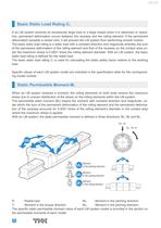
Basic Static Load Rating C0 If an LM system receives an excessively large load or a large impact when it is stationary or operative, permanent deformation occurs between the raceway and the rolling element. If the permanent deformation exceeds a certain limit, it will prevent the LM system from performing smooth motion. The basic static load rating is a static load with a constant direction and magnitude whereby the sum of the permanent deformation of the rolling element and that of the raceway on the contact area under the maximum stress is 0.0001 times the rolling element diameter. With an...
Open the catalog to page 8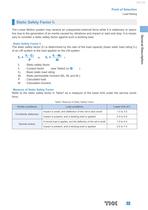
Point of Selection Load Rating Static Safety Factor fS Static Safety Factor fS The static safety factor (fs) is determined by the ratio of the load capacity (basic static load rating C0) of an LM system to the load applied on the LM system. : Static safety factor : Contact factor (see Table2 on B ) : Basic static load rating : Static permissible moment (MA, MB and MC) : Calculated load : Calculated moment Measure of Static Safety Factor Refer to the static safety factor in Table1 as a measure of the lower limit under the service conditions. Table1 Measure of Static Safety Factor Kinetic conditions...
Open the catalog to page 9
Life Calculation Formula The nominal life (L) of an LM system is obtained from the following equation using the basic dynamic load rating (C) and the applied load (P). LM System Using Balls LM System Using Rollers : Nominal life : Basic dynamic load rating : Applied load In most cases, it is difcult to calculate a load applied on an LM system. In actual use, most LM systems receive vibrations and impact during operation, and uctuation of the loads applied on them is assumed. In addition, the hardness of the raceway and the temperature of the LM system unit greatly affect the service life. With...
Open the catalog to page 10
Point of Selection Life Calculation Formula If the temperature of the environment surrounding the operating LM System exceeds 100 , take into account the adverse effect of the high temperature and multiply the basic load ratings by the temperature factor indicated in Fig.2. In addition, the LM system must be of high temperature type. Note) If the temperature of the service environment exceeds 80 , it is necessary to change the materials of the seal and end plate to high-temperature materials. Note) If the temperature of the environment exceeds 120 , it is necessary to provide dimensional stabilization....
Open the catalog to page 11All THK catalogs and technical brochures
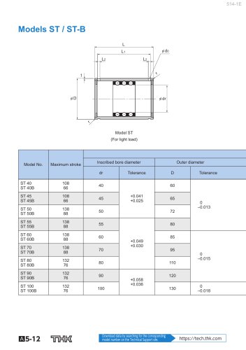 Models ST / ST-B
2 Pages
 Predicting the Rigidity
5 Pages
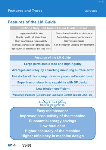 Features of the LM Guide
16 Pages
 PCT/PC
40 Pages
 Models SHS-C and SHS-LC
2 Pages
 Models SSR-XW and SSR-XWM
2 Pages
 Models SSR-XV and SSR-XVM
2 Pages
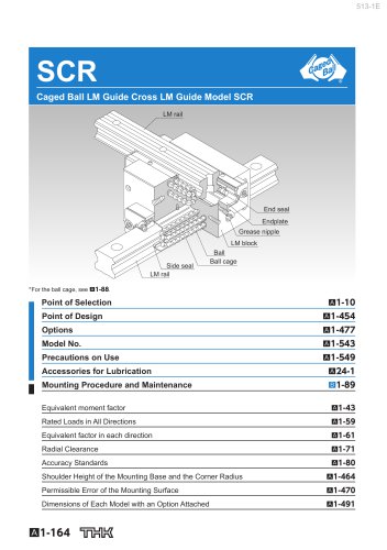 SCR
SCR8 Pages
 LM ACTUATOR GL
20 Pages
 HDR
HDR28 Pages
 RSX
RSX6 Pages
 Fix Stages
4 Pages
 Finite Stroke LM Guide EPF
12 Pages
 LM ACTUATOR GL-N
28 Pages
 LM Actuator TY
16 Pages
 Clean-Room Actuator Model CSKR
20 Pages


Archived catalogs
 Model SSR-XTB
2 Pages
 Low Price Actuator Model VLA
16 Pages
 LM Guide Actuator Model KR
92 Pages
 Ball Spline Series
24 Pages
 Cross-Roller Ring Series
28 Pages
 High-temparature LM Guide Series
28 Pages
 Model HR Separate Type
20 Pages
 LM Actuator Model TY
16 Pages
 Guide Ball Bush LG
8 Pages
 Limited-stroke LM Guide
12 Pages
 LM Actuator Model GL-N
28 Pages
 RoD Actuato
12 Pages
 Product Ordering Guide
8 Pages
 LM Guide Actuator KR
68 Pages


- Nut
- Metal nut
- THK linear guide
- Metal stand
- Plain bearing
- Bearing unit
- Metal plain bearing
- Slewing bearing
- Telescopic slide
- Steel linear guide
- THK ball bearing linear guide
- Rod end
- Metal bushing
- Ball screw
- Slide carriage block
- Cantilever axis
- THK compact linear guide
- Single-row slewing ring
- THK precision linear guide
- Ball bearing bearing unit