Group: SMC

Catalog excerpts

Air Cylinder ø20, ø25, ø32, ø40 Overall length shortened Shortened height New mounting band for auto switch Mounting height approx. Current product ø40 (CM2 series) (Compared with the current CM2B series, ø40, 50 mm stroke) Current product
Open the catalog to page 1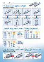
Various cover types available Direct mounting is possible. f f f Basic (Female thread on rod cover) Basic (Female thread on both covers) Male thread on both covers Male thread on rod cover Overall length shortened Weight reduced (Compared with the current product (CM2 series)) <Basic (Female thread on rod cover), Female rod end> Female thread on rod cover Overall length (Compared with the current CM2 series, at 50 mm stroke (without magnet)) *1 For basic type (female thread on rod cover) of the JCM series Male and female rod ends available Male and female threads available. Port...
Open the catalog to page 2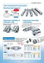
( New mounting band for auto switch) Improved mounting workability To mount the auto switch, simply insert it and position it correctly. * When the auto switch mounting band is ordered at the same time as the cylinder, it will be shipped mounted on the cylinder. Related components A more compact and lightweight combination is possible by using the JCM series with a JT series floating joint. Reduction of length when using JT and JCM Max. 77 mm Overall Length Comparison
Open the catalog to page 3
Air Cylinder Double Acting, Single Rod JCM Series 020, 025, 032, 040 Cr°hs> Without auto switch With auto switch Number of auto switches With auto switch (Built-in magnet) Port thread type Nil Cylinder stroke [mm] Refer to “Standard Strokes” on page 4. Auto switch | Nil | Without auto switch~ * For applicable auto switches, refer to the table below. *1 For M and MZ only. Mounting nut is shipped together with the product, but not assembled. Applicable Auto Switches/Refer to the Web Catalog or Best Pneumatics for further information on auto switches. *1 Water resistant type auto switches...
Open the catalog to page 4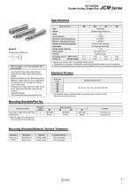
Double Acting, Single Rod JCM Series Standard Strokes *1 Intermediate strokes not listed above are produced upon receipt of order. The minimum stroke is 25 mm. Double acting, Single rod Refer to pages 11 to 13 for cylinders with auto switches. • Auto Switch Proper Mounting Position (Detection at stroke end) and Mounting Height • Minimum Stroke for Auto Switch Mounting • Method of Mounting Two Auto Switches at the Stroke End of a Cylinder for Strokes Less Than 20 mm • Precautions for Mounting Two D-M9 In-line Entry Type Auto Switches on the Same Surface • Operating Range • Auto Switch...
Open the catalog to page 5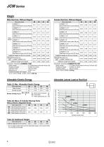
Male Rod End, Without Magnet[kg] Bore size [mm] Female Rod End, Without Magnet[kg] * Do not apply a lateral load over the allowable range to the rod end when it is mounted horizontally.
Open the catalog to page 6
Air Cylinder Double Acting, Single Rod Basic (Female Thread on Rod Cover) (BZ) JC D MBZ Bore size Port thread type Width across flats KA Width across flats B1 Port thread Female thread MM Depth A1 Port Thread: M5 Bore size Width across flats 6 length 3.5 M8 x 1.25 Width across flats 8 length 3.5 M10 x 1.25 Width across flats 8 length 3.5 M10 x 1.25 Width across flats 12 length 3.5 M14 x 1.5 Bore size Bore size Female Rod End Bore size Bore size ∗ ( ): Dimensions of built-in magne
Open the catalog to page 7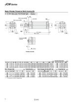
JCM Series Basic (Female Thread on Both Covers) (B) JC D MB Bore size Port thread type Width across flats KA Port thread Width across flats B1 Female thread MM Depth A1 Port Thread: M5 Bore size Width across flats 6 length 3.5 Width across flats 8 length 3.5 Width across flats 8 length 3.5 Width across flats 12 length 3.5 Bore size Bore size ∗ ( ): Dimensions of built-in magnet type Bore size
Open the catalog to page 8
Air Cylinder Double Acting, Single Rod Male Thread on Both Covers (M) JC D MM Bore size Port thread type Port thread Female thread MM Depth A1 Width across flats KA Width across H1 flats KA Width across flats B1 Effective thread length 2 x FL Width across flats 6 length 3.5 Width across flats 8 length 3.5 Width across flats 8 length 3.5 Width across flats 12 length 3.5 Port Thread: M5 Bore size Female Rod End Bore size Port Thread: Rc1/8, NPT1/8 Bore size Bore size Female Rod End Bore size ∗ ( ): Dimensions of built-in magne
Open the catalog to page 9
Port Thread: M5 [mm] Female Rod End [mm] Port Thread: Rc1/8, NPT1/8 [mm] Female Rod End [mm] 9
Open the catalog to page 10
IJCM Series Mounting Nut/Material: Carbon steel [mm]
Open the catalog to page 11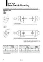
IJCM Series Auto Switch Mounting Auto Switch Proper Mounting Position (Detection at stroke end) and Mounting Height Solid state auto switch D-M9D D-M9DW D-M9DA ( ): Dimension of the D-M9DA. A and B are the dimensions from the end of the head cover/rod cover to the end of the auto switch. ( ): Dimension of the D-M9DAV. A and B are the dimensions from the end of the head cover/rod cover to the end of the auto switch. When the cylinder is shipped from the factory, the set screw of the auto switch mounting band is sometimes mounted facing 180° in the opposite direction of the figure above. Auto...
Open the catalog to page 12
Auto Switch Mounting JCM Series n: Number of auto switches [mm] * Values which include hysteresis are for guideline purposes only, they are not a guarantee (assuming approximately ±30% dispersion) and may change substantially depending on the ambient environment. * When an auto switch is used, mount it at the center of the operating range. The correct mounting position of the D-M9 is 3 mm from the end face of the switch holder (dimensions A and B).
Open the catalog to page 13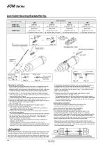
<Mounting the Auto Switch> * When the cylinder is ordered fitted with an auto switch, it is shipped with the auto switch mounting band installed. In this case, only step ® is necessary. The installation position of the auto switch mounting band serves only as a rough guide, so check the operating condition of the auto switch and then readjust the band. © As shown in Fig. 1-1, turn the set screw (c) into the nut (M3) of the auto switch mounting band (b. Hereafter called “band”) in the clockwise direction from the bottom side of the nut. * When mounting the set screw, take care that it does...
Open the catalog to page 14All SMC PNEUMATIC catalogs and technical brochures
-
 SYJ300/500/700 Series
62 Pages
-
 Vacuum Unit ZK2 Series
60 Pages
-
 Air Cylinder CJ2 Series
117 Pages
-
 AS-FS Series
36 Pages
-
 IDF series
12 Pages
-
 MHL2 Series
24 Pages
-
 EX245 Series
12 Pages
-
 Pin Cylinder CJP2/CDJP2/CJP
19 Pages
-
 5 Port Solenoid Valve VQC
63 Pages
-
 5 Port Solenoid Valve VQ
79 Pages
-
 SY
SY268 Pages
-
 5-p0979-0980-hep500
2 Pages
-
 5-p0977-0978-aep100
2 Pages
-
 5-p0966-0971-lmu
5 Pages
-
 5-p0960-0966-alb900
6 Pages
-
 5-p0956-0960-ald600
5 Pages
-
 5-p0948-0950-al800
3 Pages
-
 es70-44c-vx2
52 Pages
-
 es50-37-kq2
124 Pages
-
 ex-pcw
23 Pages
-
 1-p2124-2152-ex510
29 Pages
-
 1-p2111-2122-ex500
12 Pages
-
 1-p2063-2073-ex260
11 Pages
-
 4-p0147-0178-msu-mds
32 Pages
-
 es20-230b-crb2
59 Pages
-
 1-p1869-1878-vp3145
10 Pages
-
 VP300/500/700 series
42 Pages
-
 1-p1789-1829-vqz100
41 Pages
-
 1-p1727-1788-syj300
62 Pages
-
 5 Port Solenoid Valve S0700
111 Pages
-
 5 Port Solenoid Valve VF
59 Pages
-
 5 Port Solenoid Valve SV
127 Pages
-
 VH
VH9 Pages
-
 CUJ
CUJ41 Pages
-
 AL
AL3 Pages
-
 kj mm
kj mm9 Pages
-
 AQ
AQ4 Pages
-
 SY3000/5000-X13
2 Pages
-
 Series MB
24 Pages
-
 Series LES
23 Pages
-
 Series LEFB
16 Pages
-
 Series PF3W
28 Pages
-
 Series IDG?A/IDG
56 Pages
-
 Floating Joint
7 Pages
-
 Series IZS40/41/42
32 Pages
-
 Series LEY
7 Pages
-
 Series VHS
12 Pages
-
 Series CY1S
28 Pages
-
 SeriesCQ2/CQS/CQ
4 Pages
-
 In-line Air Filter
12 Pages
-
 5 Port Solenoid Valve
60 Pages
-
 Series CQ2/CQS
2 Pages
-
 AS series
2 Pages
-
 corporate guide
13 Pages
-
 ZP
ZP69 Pages
-
 ZFA
ZFA14 Pages
-
 ZA
ZA13 Pages
-
 MHF
MHF32 Pages
-
 MHZ
MHZ68 Pages
-
 CRB
CRB44 Pages
-
 D
D117 Pages
-
 RB
RB23 Pages
-
 CEP
CEP44 Pages
-
 RSK
RSK30 Pages
-
 CLK
CLK51 Pages
-
 MK
MK20 Pages
-
 GLJ
GLJ65 Pages
-
 MGJ
MGJ7 Pages
-
 Mx
Mx36 Pages
-
 MXH
MXH18 Pages
-
 My3
My356 Pages
-
 my1b
my1b20 Pages
-
 CC
CC15 Pages
-
 J
J14 Pages
-
 CQ2
CQ251 Pages
-
 standard cylinder
84 Pages
-
 VFN
VFN6 Pages
-
 SY3000
246 Pages
-
 SJ3A6
SJ3A618 Pages
-
 1301/IW
14 Pages
-
 CHQ/CHDQ
19 Pages
-
 AC
AC95 Pages
-
 HAW
HAW4 Pages
-
 HAA
HAA3 Pages
-
 ZB
ZB24 Pages
-
 CRB2
CRB235 Pages
-
 CJ1
CJ15 Pages
-
 SYJ
SYJ62 Pages
-
 SJ
SJ78 Pages


