SITEMA Safety Brake general Information TI-B10
1 /4Pages

SITEMA Safety Brake general Information TI-B10
1 /4Pages
Catalog excerpts
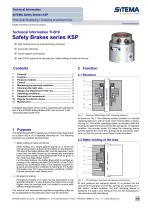
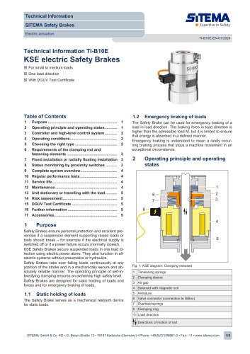
Technical Information SITEMA Safety Brakes KSP Pneumatic Releasing / Clamping at pressure loss TI-B10-EN-06/2013 English translation of German original Safety Brakes series KSP high holding forces by self-intensifying clamping pneumatic releasing secure against overloading with DGUV approval for intended use “static holding of loads and forces” load direction A detailed description of the control, assembly and operational test of the SITEMA Safety Brakes KSP can be found in the “Operating Manual BA-B10”. Fig. 1: 1 Purpose The Safety Brake KSP is designed and built to hold raised loads on a piston rod or on a separate clamping rod. The following purposes are possible and permitted: Structure Safety Brake KSP; clamping released As shown in Fig. 1, the clamping system consists of a conical clamping sleeve (1) with an outer cone moving within a clamping ring (2). This whole clamping system is movable inside the housing (3) against the force of the disc springs (4). In released condition, the annular piston (5) keeps the clamping sleeve pushed against the set of disc springs (6) by pneumatic pressure, so that the rod can move freely in both directions. 2.2 Static holding of the load 1. Static holding of loads and forces 6 1 2 4 5 load direction Static holding of a weight against gravity on a round rod and securing load to prevent it from falling in one direction. The size of the Safety Brake KSP must be selected in such a way that the static forces do not exceed the admissible load (nominal load M) of the Safety Brake KSP as given in the „Technical Data Sheet TI-B11“. For this static holding, the Safety Brake KSP is certified according to the testing principle GS-HSM-02 of the DGUV (testing and certification body of the statutory accident insurance and prevention institution in Germany). For further information see “EC type-examination certificate TI-B40“, Internet download: www.sitema.com. 2. Emergency braking Emergency braking of a mass moving downwards in the specified direction. In this direction the brake force is high (higher than the nominal load) but limited to ensure welldefined energy dissipation. The national and international regulations regarding safety as far as applicable to the particular case must be observed. Rod clamped, maximum load equals nominal load At zero pressure the clamping sleeve (1) is pushed into the cone of the housing by a set of disc springs (6), whereby an initial friction contact between rod and clamping sleeve is achieved. If a load is now acting on the rod, the clamping process becomes self-intensifying. SITEMA GmbH & Co.KG . Im Mittelfeld 10 . D-76135 Karlsruhe . Phone: +49 (0)721 98661-0 . Fax: -11 . www.sitema.com
Open the catalog to page 1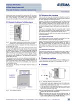
Technical Information SITEMA Safety Brakes KSP Pneumatic Releasing / Clamping at pressure loss TI-B10-EN-06/2013 Acting force does not exceed the nominal load M, the movement of the rod is very small, typically under 0.5 mm. The position of the clamping ring remains in its original position, because the spring force V (4) is somewhat larger than M. 2.3 Dynamic braking of a falling mass 6 load direction 2.4 Releasing the clamping If the rod did not move after clamping and therefore no load is was transferred to the safety brake, the clamp may be opened by simply applying the operating pressure....
Open the catalog to page 2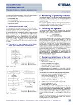
Technical Information SITEMA Safety Brakes KSP Pneumatic Releasing / Clamping at pressure loss TI-B10-EN-06/2013 If a particular quick response time of the KSP Safety Brake is required, the following preconditions must be met: • quick exhaust valve • short line distances • correspondingly large valve and line cross-sections • appropriate control 4.1 Activation using 3/2-way valve In most cases, the activation indicated in Fig. 5 will be used. During every operational cycle, the 3/2-way valve is actuated electrically and releases the Safety Brake KSP. In all other operational conditions, as well...
Open the catalog to page 3
Technical Information SITEMA Safety Brakes KSP Pneumatic Releasing / Clamping at pressure loss TI-B10-EN-06/2013 8 Operating conditions SITEMA Safety Brakes KSP are designed to operate in normal clean and dry workshop atmosphere. Heavy soiling conditions like grinding dust, chips, other liquids, etc. may require special protective measures. In such cases, please contact SITEMA. The permissible surface temperature is 0 - 60°C. 9 Required risk assessment It must be ensured that the dimensions and arrangement of a SITEMA Safety Brake KSP used in safety-relevant applications meet the requirements...
Open the catalog to page 4All SITEMA catalogs and technical brochures
 electric Safety Brake linear
2 Pages
 PowerStroke SITEMA
9 Pages
 SITEMA_Flyer_2020
2 Pages
 TI-S10 Safety Locks
4 Pages
 TI-A10
7 Pages
 TI-P30
1 Page
 SITEMA Applications
2 Pages
 Dimensions, type KRG
1 Page
 Dimensions, type KRP/T
1 Page
 Dimensions, type KRP
1 Page
 Dimensions, type KR, K
2 Pages
 SITEMA Safety Catchers
2 Pages
 SITEMA Locking Units KFH
6 Pages
 STB10 Rod Attachment STB
3 Pages
 F60 Dimensions, type KFHA
6 Pages
 Z10 - Auto Bleeder
3 Pages
 SITEMA Safety Locks KRG
1 Page
 SITEMA company
15 Pages
 Locking Units KFPC
3 Pages
 Locking units series KFPA
4 Pages


- Cylinder
- Lifting table
- Double-acting cylinder
- Scissor lift table
- Hydraulic cylinder
- Pneumatic cylinder
- Stationary lift table
- Friction brake
- Hydraulic lift table
- Industrial cylinder
- Standard cylinder
- ISO cylinder
- Electromagnetic brake
- Industrial control system
- Heavy load lift table
- Cylinder with piston rod
- Hydraulic clamping
- Monitoring control system