SITEMA Safety Brake Data sheet TI-B11
1 /1Page

SITEMA Safety Brake Data sheet TI-B11
1 /1Page
Catalog excerpts

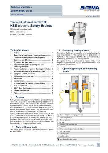
Technical Data Sheet SITEMA Safety Brakes KSP Pneumatic Releasing / Clamping at pressure loss TI-B11-EN-05/2013 English translation of German original Technical Data Sheet TI-B11 Safety Brakes series KSP (with DGUV approval) General information, particularly regarding purpose, function, choosing the right size and control is provided in “Technical Information TI-B10”. Furthermore important practical advices are given in the “Operating Manual BA-B10”. attachment side Holder for proximity switch 1 Signal “load secured” see 5 Holder for proximity switch 2 Signal “clamping released” see 5 load direction Dimensions Safety Brake KSP(CAD-Files download from www.sitema.com) Port - pressure compensation see 6 Pressure port - release see 2 Subject to modification without prior notice 1 M is the admissible force the mass to be secured exerts on the clamping device. The holding (braking) force for dry or mineral-oil wetted shafts is not less than 2 x M, but will not exceed 3,5 x M. 2 p is the pressure required for releasing. The permissible working pressure is 8 bar. 3 Regarding safety it is an advantageous feature of the Safety Brake KSP, that it normally will not release unless not only pressure is applied but also the load is supported by the lifting drive, thus automatically unintended releasing is prevented. However, this is only true, if the load exceeds a minimum limit which depends on the working air pressure. With for example 6 bar pressure the critical minimum load is equal to F6. Values for other pressure level will be given on request. 4 Pneumatic operating volume. 5 Proximity switch holders are provided for standard proximity switches M12x1 with a nominal switching distance of 2 mm (flush mountable). For easier service, the proximity switch holders have a depth stop and are pre-adjusted when delivered from the factory. 6 Port T is used for pressure compensation (breathing). It is plugged with an air filter element. If, however, moisture or aggressive media are present, a hose instead of the filter must be installed to connect the device with a clean atmosphere. SITEMA GmbH & Co.KG . Im Mittelfeld 10 . D-76135 Karlsruhe . Phone: +49(0)721/98661-0 . Fax: -11 . www.sitema.com
Open the catalog to page 1All SITEMA catalogs and technical brochures
 electric Safety Brake linear
2 Pages
 PowerStroke SITEMA
9 Pages
 SITEMA_Flyer_2020
2 Pages
 TI-S10 Safety Locks
4 Pages
 TI-A10
7 Pages
 TI-P30
1 Page
 SITEMA Applications
2 Pages
 Dimensions, type KRG
1 Page
 Dimensions, type KRP/T
1 Page
 Dimensions, type KRP
1 Page
 Dimensions, type KR, K
2 Pages
 SITEMA Safety Catchers
2 Pages
 SITEMA Locking Units KFH
6 Pages
 STB10 Rod Attachment STB
3 Pages
 F60 Dimensions, type KFHA
6 Pages
 Z10 - Auto Bleeder
3 Pages
 SITEMA Safety Locks KRG
1 Page
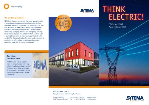
 SITEMA company
15 Pages
 Locking Units KFPC
3 Pages
 Locking units series KFPA
4 Pages


- Cylinder
- Lifting table
- Double-acting cylinder
- Scissor lift table
- Hydraulic cylinder
- Pneumatic cylinder
- Stationary lift table
- Friction brake
- Hydraulic lift table
- Industrial cylinder
- Standard cylinder
- ISO cylinder
- Electromagnetic brake
- Industrial control system
- Heavy load lift table
- Cylinder with piston rod
- Hydraulic clamping
- Monitoring control system