- Catalogs
- Silicon Designs
- Silicon Designs Model 2460 Analog Accel with ±4V Differential Output or 0.5V to 4.5V Single Ended Output, +8 to +32V DC Power
Silicon Designs Model 2460 Analog Accel with ±4V Differential Output or 0.5V to 4.5V Single Ended Output, +8 to +32V DC Power
1 /3Pages

Silicon Designs Model 2460 Analog Accel with ±4V Differential Output or 0.5V to 4.5V Single Ended Output, +8 to +32V DC Power
1 /3Pages
Catalog excerpts
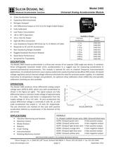
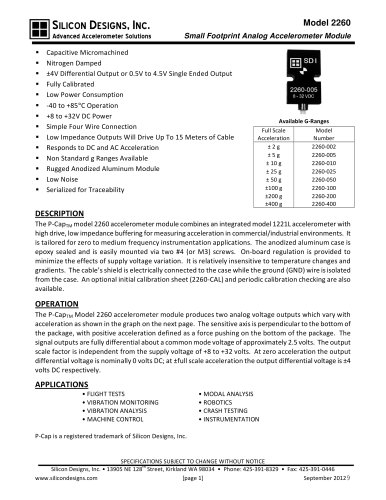
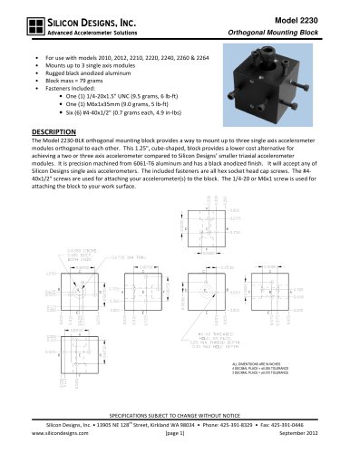
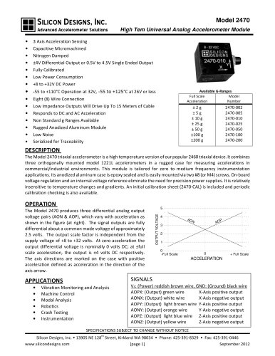
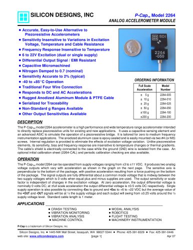
SILICON DESIGNS, INC. Advanced Accelerometer Solutions • • • • • • • • • • • • • • • Model 2460 Universal Analog Accelerometer Module 3 Axis Acceleration Sensing Capacitive Micromachined Nitrogen Damped ±4V Differential Output or 0.5V to 4.5V Single Ended Output Fully Calibrated Low Power Consumption -40 to +85°C Operation +8 to +32V DC Power Eight (8) Wire Connection Low Impedance Outputs Will Drive Up To 15 Meters of Cable Responds to DC and AC Acceleration Non Standard g Ranges Available Rugged Anodized Aluminum Module Good Noise Performance Serialized for Traceability Available G-Ranges Full Scale Model Number Acceleration ±2g ±5g ± 10 g ± 25 g ± 50 g ±100 g ±200 g ±400 g 2460-002 2460-005 2460-010 2460-025 2460-050 2460-100 2460-200 2460-400 DESCRIPTION The Model 2460 triaxial accelerometer is a three-axis version of our popular 2260 single axis device. It combines three orthogonally mounted model 1221L accelerometers in a rugged case for measuring accelerations in commercial/industrial environments. This module is tailored for zero to medium frequency instrumentation applications. Its anodized aluminum case is epoxy sealed and is easily mounted via two #8 (or M4) screws. On-board voltage regulation and an internal voltage reference eliminate the need for precision power supplies. It is relatively insensitive to temperature changes and gradients. An optional initial calibration sheet (2460-CAL) and periodic calibration checking are also available. OPERATION 4 AO N P AO 3 2 1 0 -Full Scale 0 + Full Scale ACCELERATION SIGNALS APPLICATIONS • • • • • • • 5 OUTPUT VOLTAGE The Model 2460 produces three differential analog output voltage pairs (AON & AOP), which vary with acceleration as shown in the figure (at right). The signal outputs are fully differential about a common mode voltage of approximately 2.5 volts. The output scale factor is independent from the supply voltage of +8 to +32 volts. At zero acceleration the output differential voltage is nominally 0 volts DC; at ±full scale acceleration the output is ±4 volts DC respectively. The axis directions are marked on the case with positive acceleration defined as acceleration in the direction of the axis arrow. Vibration Monitoring and Analysis Machine Control Modal Analysis Robotics Crash Testing Instrumentation Rotating Machinery Control VS: (Power) reddish brown wire, GND: (Ground) black wire AOPX: (Output) green wire X-Axis positive output AONX: (Output) white wire X-Axis negative output AOPY: (Output) light brown wire Y-Axis positive output AONY: (Output) orange wire Y-Axis negative output AOPZ: (Output) light blue wire Z-Axis positive output AONZ: (Output) yellow wire Z-Axis negative output SPECIFICATIONS SUBJECT TO CHANGE WITHOUT NOTICE th Silicon Designs, Inc. • 13905 NE 128 Street, Kirkland WA 98034 • Phone: 425-391-8329 • Fax: 425-391-0446 www.silicondesigns.com [page 1] September 2012
Open the catalog to page 1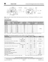
39.4 [1000] SILICON DES IG N S 2460-XXX Y X 0.125 [3.2] XXXX X 0.388 [9.9] .748 [19.0] .118 [3.0] .985 [25.0] 8 - 32 VDC SERIAL # Z 0.585 [14.9] .175 [4.4] DIA .825 [21.0] .985 [25.0] .748 [19.0] 0.448 [11.4] Universal Analog Accelerometer Module Model 2460 Inch [mm] .118 [3.0] Note: The cable’s braided shield is electrically connected to the case. The black ground (GND) wire is isolated from the case. PERFORMANCE By Model: VS=+8 to +32VDC, TC=25°C. MODEL Input Frequency Response Sensitivity, Output Noise, Differential Max. Mechanical 1 2 NUMBER Range (Nominal, 3 dB) Differential (RMS, typical)...
Open the catalog to page 2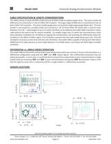
Universal Analog Accelerometer Module Model 2460 CABLE SPECIFICATION & LENGTH CONSIDERATIONS The cable consists of seven 28 AWG (7x36) and one 26 AWG (7x34) tin-plated copper wires. The seven smaller 28 AWG wires are covered by 5.5 mils of Teflon FEP insulation. The larger single 26 AWG wire is covered by 8.5 mils of black Teflon FEP insulation. The seven smaller gauge wires surround the single larger gauge (black) wire. The wire bundle is surrounded by a braided shield and covered by a 10 mil thick Teflon FEP jacket with a nominal outer diameter of 0.136”. Cable lengths of up to 15 meters (50...
Open the catalog to page 3All Silicon Designs catalogs and technical brochures
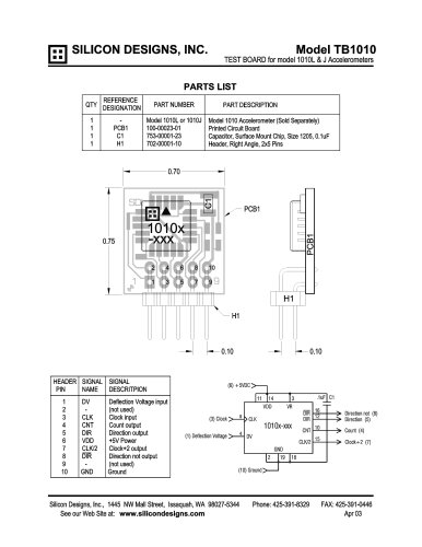
 Silicon Designs Model 1010
8 Pages
 LG Series
3 Pages
 Model 3320 G-Logger
2 Pages