- Catalogs
- Silicon Designs
- Silicon Designs Model 2422 Triaxial Analog Accel Module, ±4V Differential or 4V Single Ended Output, +5 VDC Power
Silicon Designs Model 2422 Triaxial Analog Accel Module, ±4V Differential or 4V Single Ended Output, +5 VDC Power
1 /3Pages

Silicon Designs Model 2422 Triaxial Analog Accel Module, ±4V Differential or 4V Single Ended Output, +5 VDC Power
1 /3Pages
Catalog excerpts
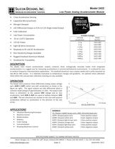
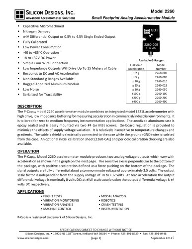
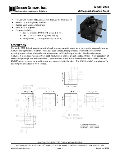
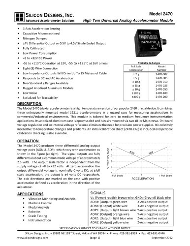
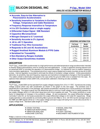
SILICON DESIGNS, INC. Model 2422 Advanced Accelerometer Solutions Low Power Analog Accelerometer Module • 3 Axis Acceleration Sensing • Capacitive Micromachined • Nitrogen Damped • ±4V Differential Output or 0.5V to 4.5V Single Ended Output • Fully Calibrated • Low Power Consumption • -55 to +125°C Operation • +5V DC Power • Eight (8) Wire Connection • Responds to DC and AC Acceleration • Non Standard g Ranges Available • Rugged Anodized Aluminum Module • Serialized for Traceability Available G-Ranges Full Scale Model Acceleration Number ±2g ±5g ± 10 g ± 25 g ± 50 g ±100 g ±200 g ±400 g 2422-002 2422-005 2422-010 2422-025 2422-050 2422-100 2422-200 2422-400 DESCRIPTION The Model 2422 triaxial accelerometer module combines three orthogonally mounted model 1210 integrated accelerometers in a rugged case for measuring accelerations in commercial/industrial environments. It is tailored for zero to medium frequency instrumentation applications. The anodized aluminum case is epoxy sealed and is easily mounted via two #8 (or M4) screws. It is relatively insensitive to temperature changes and gradients. An optional initial calibration sheet (2422-CAL) and periodic calibration checking are also available. OPERATION 5 OUTPUT VOLTAGE The Model 2422 produces three differential analog output voltage pairs (AON & AOP), which vary with acceleration as shown in the figure (at right). The signal outputs are fully differential about a common mode voltage of approximately 2.5 volts. The output scale factor is ratiometric to the applied VDD voltage and at zero acceleration, both AON & AOP are equal to halfway between VDD and GND. The axis directions are marked on the case with positive acceleration defined as acceleration in the direction of the axis arrow. 4 AO N P AO 3 2 1 0 -Full Scale 0 + Full Scale ACCELERATION APPLICATIONS • • • • • • • SIGNALS Vibration Monitoring & Analysis Machine Control Modal Analysis Robotics Crash Testing Instrumentation Rotating Machinery Control VS: (Power) reddish brown wire, GND: (Ground) black wire AOPX: (Output) green wire X-Axis positive output AONX: (Output) white wire X-Axis negative output AOPY: (Output) light brown wire Y-Axis positive output AONY: (Output) orange wire Y-Axis negative output AOPZ: (Output) light blue wire Z-Axis positive output AONZ: (Output) yellow wire Z-Axis negative output SPECIFICATIONS SUBJECT TO CHANGE WITHOUT NOTICE th Silicon Designs, Inc. • 13905 NE 128 Street, Kirkland WA 98034 • Phone: 425-391-8329 • Fax: 425-391-0446 www.silicondesigns.com [page 1] September 2012
Open the catalog to page 1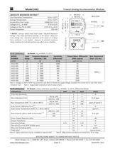
Triaxial Analog Accelerometer Module Model 2422 .985 [25.0] .748 [19.0] * NOTICE: Stresses above those listed under "Absolute Maximum Ratings" may cause permanent damage to the device. These are stress ratings only. Functional operation of the device at or above these conditions is not implied. Exposure to absolute maximum rating conditions for extended periods may affect device reliability. .748 [19.0] .118 [3.0] .166 [4.2] DIA +5V ONLY SILICON DESIGNS 2422-XXX Y X 39 [1000] SERIAL # .118 [3.0] .825 [21.0] -55 to +125°C -55 to +125°C 2000g for 0.1 ms -0.5V to 6.5V -0.5V to VDD+0.5V 250 mW .985...
Open the catalog to page 2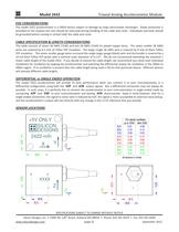
Triaxial Analog Accelerometer Module Model 2422 ESD CONSIDERATIONS The model 2422 accelerometer is a CMOS device subject to damage by large electrostatic discharges. Diode protection is provided on the outputs but care should be exercised during handling of the cable wire ends. Individuals and tools should be grounded before coming in contact with the cable wire ends. CABLE SPECIFICATION & LENGTH CONSIDERATIONS The cable consists of seven 28 AWG (7x36) and one 26 AWG (7x34) tin plated copper wires. The seven smaller 28 AWG wires are covered by 6.5 mils of Teflon FEP insulation. The larger single...
Open the catalog to page 3All Silicon Designs catalogs and technical brochures
 Silicon Designs Model 1010
8 Pages
 LG Series
3 Pages
 Model 3320 G-Logger
2 Pages