Catalog excerpts

FIE Series Frequency Inverter FIE Series Frequency Inverter User Manual
Open the catalog to page 1
FIE Series Frequency Inverter
Open the catalog to page 2
FIE Series Frequency Inverter
Open the catalog to page 3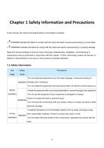
In this manual, the notices are graded based on the degree of danger: ' DANGER indicates that failure to comply with the notice will result in severe personal injury or even death. WARNING indicates that failure to comply with the notice will result in personal injury or property damage. Read this manual carefully so that you have a thorough understanding. Installation, commissioning or maintenance may be performed in conjunction with this chapter. VTdrive Technology Limited will assume no liability or responsibility for any injury or loss caused by improper operation.
Open the catalog to page 4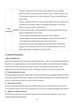
• Repair or maintenance of the AC drive may be performed only by qualified personnel. Failure to comply will result in personal injury or damage to the AC drive. • Do not repair or maintain the AC drive at power-on. Failure to comply will result in electric shock. • Repair or maintain the AC drive only ten minutes after the AC drive is powered off. This allows for the residual voltage in the capacitor to discharge to a safe value. During maintenance Failure to comply will result in personal injury. DANGER • Ensure that the AC drive is disconnected from all power supplies before starting...
Open the catalog to page 7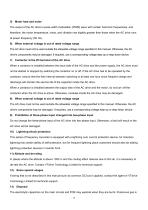
Motor heat and noise The output of the AC drive is pulse width modulation (PWM) wave with certain harmonic frequencies, and therefore, the motor temperature, noise, and vibration are slightly greater than those when the AC drive runs at power frequency (50 Hz). 6) When external voltage is out of rated voltage range The AC drive must not be used outside the allowable voltage range specified in this manual. Otherwise, the AC drive's components may be damaged. If required, use a corresponding voltage step-up or step-down device. 7) Contactor at the I/O terminal of the AC drive When a contactor...
Open the catalog to page 8
generated when the plastic parts are burnt. Treat them as ordinary industrial waste 14) Adaptable Motor • The standard adaptable motor is adaptable four-pole squirrel-cage asynchronous induction motor or PMSM. For other types of motor, select a proper AC drive according to the rated motor current. • The cooling fan and rotor shaft of non-variable-frequency motor are coaxial, which results in reduced cooling effect when the rotational speed declines. If variable speed is required, add a more powerful fan or replace it with variable-frequency motor in applications where the motor overheats...
Open the catalog to page 9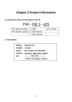
2.1 Designation Rules and Nameplate of the FIE MODEL: POWER: INPUT: OUTPUT: S/N:
Open the catalog to page 10
Figure 2-1 Inverter model and technical data
Open the catalog to page 11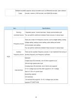
Multiple encoderIt supports various encoders such as differential encoder, open-collector Types encoder, resolver, UVWencoder, and SIN/COS encoder.
Open the catalog to page 14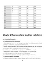
1. Ambient temperature -10"C~40"C, Well ventilated or indoor Spaces with ventilation devices, more than 40 "C derating use. Avoid vibration, direct sunlight, away from heat source. 2. AC drives can install where altitude 1000 m below the output rated power, when more than 1000 m altitude need derating use, specific derating range, please contact the company. 3. Avoid high temperature high humidity, the humidity is less than 90% RH (Non-condensate). 4. Apart from the oil, salt and corrosive gas. To prevent water, steam, dust, lint, metal powder. 5. Prevent electromagnetic interference, away...
Open the catalog to page 17
Power level The FIE series AC drive dissipates heat from the bottom to the top. When multiple AC drives are required to work together, install them side by side. For application installing multiple AC drives, if one row of AC drives need to be installed above another row, install an insulation guide plate to prevent AC drives in the lower row from heating those in the upper row and causing faults. 3.1.3 Mounting dimension 1) Online example
Open the catalog to page 18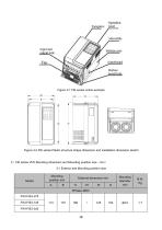
output hole Bottom case install hole Figure 3-2 FIE series Plastic structure shape dimension and installation dimension sketch 2) FIE series VFD Mounting dimension and Mounting position size (mm) 3-1 Exterior and Mounting position size
Open the catalog to page 19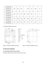
Figure 3-3 keyboard installation dimensions Figure 3-4 keyboard installation hole size 3.2 Electrical Installation 3.2.1 Description of Main Circuit Terminals Description of Main Circuit Terminals of Three-phase AC drive
Open the catalog to page 21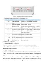
3-2 Description of Main Circuit Terminals of Three-phase AC drive 3.2.2 Precautions on the Wiring: 1) Power input terminals L1, L2 or R, S, T: • The cable connection on the input side of the AC drive has no phase sequence requirement. • The specification and installation method of external power cables must comply with the local safety regulations and related IEC standards. 2) DC bus terminals (+), (—): • Terminals (+) and (-) of DC bus have residual voltage after the AC drive is switched off. After indicator CHARGE goes off, wait at least 10 minutes before touching the equipment Otherwise,...
Open the catalog to page 22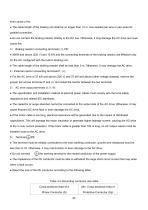
even cause a fire. ● The cable length of the braking unit shall be no longer than 10 m. Use twisted pair wire or pair wires for parallel connection. ● Do not connect the braking resistor directly to the DC bus. Otherwise, it may damage the AC drive and even cause fire. 3) Braking resistor connecting terminals (+), PB: ● 30kW and above (220 V) and 15 kW and the connecting terminals of the braking resistor are effective only for the AC configured with the built-in braking unit. ● The cable length of the braking resistor shall be less than 5 m. Otherwise, it may damage the AC drive. 4)External...
Open the catalog to page 23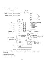
3.2.4 Wiring of AC Drive Control Circuit Braking resistor Extension card ■jqv setting frequency 'collector 1 (High-speed 'pulse output) Paul contact I output Figure 3-7 AC drives control circuit connection mode Note: All FIE series AC drives have the same wiring mode. The figure here shows the wiring of single-phase 220 VAC drive. ◎ indicates main circuit terminal o indicates control circuit terminal.
Open the catalog to page 26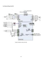
Braking unit MDBUN breaker Contactor magnetic core MultH ir'e'erce Fault contact output Fautt output
Open the catalog to page 27All VTDRIVssE Technology Limited catalogs and technical brochures
-
 Brake unit FWI-BU3 series
1 Pages
-
 VS5 Solar pump inverter
3 Pages
-
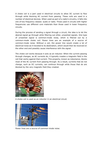 VTdrive What is a Choke Coil
2 Pages