Catalog excerpts

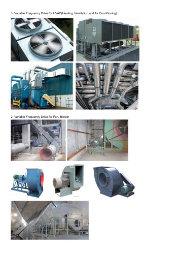
Basic design and operation principles behind variable frequency drives (VFDs) Although much has been published on variable frequency drives (VFDs), people continue to be confused by them. The intent of this article is to provide a basic overview of these devices by evaluating key features as well as their impact on a building' s electrical system. A VFD is used extensively in modern facilities to save energy on mechanical systems, such as motors, pumps, etc. Selected to match motor curves to ensure speed and loads are matched, VFDs can help save motor energy by allowing for variable flow of air, water, etc., based on the demands and needs of a particular site. This is accomplished by converting the fixed frequency of incoming alternating current (AC) voltage to direct current (DC) — and then reconverting it back to AC voltage by varying the frequency at which the insulated gate bipolar transistors (IGBTs) are gated Basic operation A VFD operates by converting the input sinusoidal AC voltage to DC voltage and then back to AC voltage. This conversion occurs by using either silicon-controlled rectifiers (SCRs) or IGBTs. The DC voltage is switched using IGBTs to create an AC output voltage (called the inverter). The IGBT can switch on and off to create an AC voltage waveform that delivers power to the motor. The IGBTs create an AC waveform by using pulse width-modulated (PWM) switching. The frequency at which the switching occurs, which varies from manufacturer to manufacturer, is called " carrier frequency." Variable frequency drive Diode bridge A typical 6-pulse VFD has six diodes as a front-end bridge rectifier that converts AC to DC. VFDs can also have 12 diodes — two sets per phase (2 X 2 X 3 = 12 pulse) — or 18 diodes — three sets per phase (3 X 2 X 3 = 18 pulse) — and so on. One set of diodes is supplied by a Delta-Y transformer to create a phase shift on the AC side
Open the catalog to page 1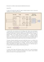
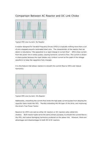
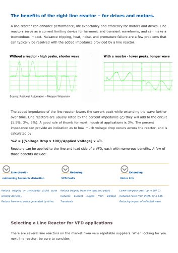
between the two rectifiers to reduce harmonics reflected back to the source. A 6-pulse VFD develops the output DC voltage by taking each phase of the AC source and installing one set of diodes to gate on and off. Rectifier Filter output filter A 6-pulse VFD is most commonly used in the building system. Typical current total harmonic distortion (THD) back to the source can be as high as 35% at the input terminals of the VFD. You can install an inline inductor to reduce the reflected harmonics back to the point of coupling, as defined by IEEE 519. The inductor reduces the current distortion —...
Open the catalog to page 2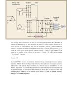
The windings of the transformers are offset to cancel the largest harmonics from the VFD. By reducing the harmonics at the input terminals, the intent is to reduce voltage distortion at the source because the current THD at each piece of equipment is reduced. Conduct a harmonic evaluation to validate the findings. Disadvantages in providing a 12-pulse VFD are the cost (i.e., it can be up to 50% more) and the physical footprint required. A 6-pulse VFD for a typical 25-hp motor can be installed on the wall next to the motor. A 12-pulse VFD will be a free-standing “switchboard” type unit....
Open the catalog to page 3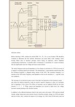
Selection criteria Before selecting a VFD, evaluate the current THD. A 6-, 12-, 18- or even 24-pulse VFD should be evaluated to determine the best solution. Harmonics can cause faulty meter readings, motor bearing failure (due to electrical currents), blown fusing on capacitors, and/or telephone communication interference. A possible effect of harmonics is excitement of a system resonance that can significantly raise the voltage and cause system failures. The carrier frequency and circuit impedance is a key feature in selection of a VFD to be aware of in regard to switching speeds and...
Open the catalog to page 4
with overvoltage condition after select restarts. You should also ensure that single-phase protection includes both time and magnitude components. How does the motor nominal rating (typically 460V) correlate with nominal voltage of VFD (typically 480V)? The system utilization voltage should be such that it does not go beyond the high voltage rating of the motor (causing increased current and prematurely burning the motor). At the same time, it should not be too low where a sag on the system voltage, combined with building voltage drop, does not shut down the VFD. When sizing the input...
Open the catalog to page 5
Reduced harmonics should be considered for soft loads (such as at the end of an electric utility feed in a rural area or when powering loads with on-site generators) to reduce the voltage THD at the point of common coupling (PCC). High voltage distortion can cause malfunction of electronic devices. Ensure the VFD output conductors are sized per manufacturer recommendations, and consider adding output line reactors. The line reactors should be sized to match the distance requirements of a VFD that is not located near the motor load. Sizing of the electrical infrastructure should take into...
Open the catalog to page 6All VTDRIVssE Technology Limited catalogs and technical brochures
-
 Brake unit FWI-BU3 series
1 Pages
-
 VS5 Solar pump inverter
3 Pages
-
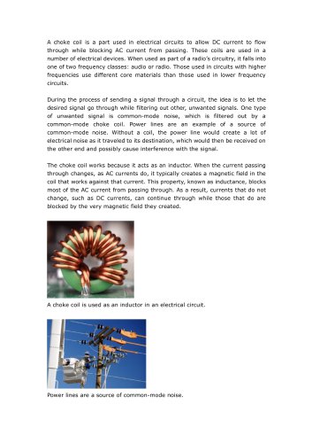 VTdrive What is a Choke Coil
2 Pages