


- Company
- Products
- Catalogs
- News & Trends
- Exhibitions
Ex Protection – ATEX Explosion Protection Catalogue

Ex Protection – ATEX Explosion Protection Catalogue
The document provides an overview of explosion protection measures in compliance with ATEX Directives, crucial for safety in explosive atmospheres. It emphasizes the importance of adhering to these directives in Europe and their impact on safety protocols.
The catalogue details various safety-monitoring modules, safety switches, solenoid interlocks, position switches, and safety sensors designed for explosion protection. Each product is listed with specific model numbers and applications.
Products like PROTECT SRB 101EXi and SRB 200EXi are highlighted for monitoring safety conditions in explosive environments.
Models such as EX-AZ 16-…-3D and EX-AZ 335-…-3D are described, emphasizing their use in securing machinery and preventing unauthorized access.
Devices like EX-AZM 170-…-3G/D and EX-Z/T 235-…-3D are crucial for maintaining operational safety by ensuring machinery operates only under safe conditions.
Control devices like EX-RDT and indicator lights provide visual and operational feedback in hazardous environments.
Systems such as EX-SHGV-…-3G/D ensure machinery cannot be operated unless specific safety conditions are met.
The catalogue emphasizes the availability of online resources, including technical data, conformity declarations, and CAD drawings, accessible in multiple languages to support designers and engineers.
Contact information for Schmersal's global offices is provided, highlighting their commitment to worldwide support and services.
The document discusses the harmonization of explosion protection standards in Europe, focusing on directives 94/4/EC and 1999/92/EC, which standardize protection against gas and dust explosions.
Various sources of ignition are identified, including sparks, electric arcs, hot surfaces, and more, linked to specific causes like mechanical friction or electrical faults.
Explosions require a flammable substance, oxygen, and an ignition source. The document explains conditions for explosions, including concentration ratios for gases and dusts.
Potentially explosive areas are classified into zones based on the frequency and duration of explosive atmospheres, helping determine necessary protective measures and equipment selection.
Users must perform a risk analysis and document explosion protection measures, including classifying areas into zones and maintaining up-to-date documentation.
The document outlines various types of explosion protection, including mechanical protection and specific standards like EN 60079-15 for zone 2 areas.
The document emphasizes the importance of adhering to standardized explosion protection measures and maintaining comprehensive documentation for safety.
- Oil Immersion "o": Prevents explosions by immersing the ignition source in oil.
- Pressurized Enclosures "p": Maintains positive pressure with protective gas to prevent explosive atmospheres.
- Powder Filling "q": Surrounds ignition sources with granular material to prevent arcs from igniting explosive atmospheres.
- Flameproof Enclosures "d": Withstand internal explosions and prevent transmission.
- Increased Safety "e": Prevents excessive temperatures and sparks.
- Encapsulation "m": Encloses ignition sources to prevent sparking or heating.
- Intrinsic Safety "i": Limits current, voltage, and energy to prevent ignition.
- Limits electrical energy to prevent sparks and excessive heating.
- Uses Zener diodes for voltage limitation and resistors for current limitation.
- Maximum power is calculated using specific formulas and standards.
- Systems are classified into "ia", "ib", and "ic" based on protection levels.
- Design involves ensuring voltage, current, and power limits are not exceeded.
- Equipment must meet application requirements and prevent ignition hazards.
- Surface temperatures and mechanically generated sparks must be controlled.
- Materials used must adhere to specific composition limits to prevent ignition.
- Equipment must be clearly marked for its application and protection level.
- Operating instructions must detail conditions for safe use.
- SRB 101Exi: Features include 1 or 2 channel control, 1 safety enabling circuit, and optional cross-wire short detection. Certified for use in zones 1/21 and can be installed in zone 2.
- SRB 200Exi: Similar to SRB 101Exi but with 2 safety releases. Suitable for emergency stop control devices.
- Both modules operate at a rated voltage of 24 VDC with a maximum safety voltage of 253 VAC.
- Protection class of IP 40 for the enclosure and IP 20 for terminals, with a wiring compartment rated at IP 54.
- Designed to handle ambient temperatures from -25°C to +60°C and have a mechanical life of 107 operations.
- Designed for DIN rail mounting and housed in a thermoplastic enclosure.
- Comply with various safety standards, including DIN EN ISO 13849-1:2007 and ATEX 94/9/EG.
- Safety functions include detection of cable breaks, cross-wire shorts, and earth leakages.
- Various safety switches and sensors, such as the EX-AZ series and EX-BNS series, suitable for use in explosive atmospheres.
- Designed with features like multiple coding, high contact reliability, and are not sensitive to dirty conditions.
- Contact Types: Options include 1 NO/2 NC, 3 NC, and change-over contacts with double break and galvanically separated bridges.
- Switching System: Slow action, NC contact with positive break as per IEC 60947-5-1.
- Connection: Screw terminals supporting cable sections from 0.75 mm² to 2.5 mm².
- Cable Entry: M20 with options for multiple entries.
- Electrical Ratings: Uimp of 4 kV, Ui of 250 V, and Ithe of 10 A. Utilization categories include AC-15 and DC-13 with Ie/Ue of 4 A/230 VAC and 4 A/24 VDC.
- Mechanical Life: Up to 10 million operations.
- Environmental Conditions: Operating temperatures range from -20°C to +60°C, with protection class IP67.
- Actuator heads can be repositioned in 90° steps, allowing for 8 actuating planes.
- Mounting details conform to EN 50041, with options for flat surface mounting and various actuator types (straight, angled, flexible).
- Actuators must be ordered separately, and specific tools like a Torx T10 screwdriver are required for adjustments.
- Compliant with EN 60947-5-1, EN 61241-0, EN 61241-1, and BG-GS-ET-15.
- Ex certified for use in hazardous dust zones (Ex tD A22 IP67 T90°C X).
- Products are identified by specific codes indicating contact configuration, latching force, and additional features like gold-plated contacts.
- Various system components and accessories are available, including EX-certified cable glands and lockout tags.
- High contact reliability with low voltages and currents.
- Long mechanical life and robust construction with metal enclosures.
- Adjustable latching forces and spring-loaded actuators for enhanced safety.
Key features include long life, double insulation, high holding force (2000 N for EX-AZM 161 and 3500 N for EX-AZM 415), and large wiring compartments. Designed for power to unlock or lock, with options for cage clamps or screw terminals and multiple cable entries.
Certified for Ex protection (Ex tD A22 IP67) and comply with standards such as EN 60947-5-1 and EN 61241. Enclosures made from materials like glass-fibre reinforced thermoplastic or light-alloy die-cast, with protection classes up to IP 67. Support various contact types and configurations, including change-over contacts with double break and galvanically separated contact bridges.
Ordering details for different configurations, specifying options for latching force, power to unlock or lock, and contact variants. Approvals and certifications are highlighted, ensuring compliance with safety and operational standards.
Manual release options are available for maintenance purposes, and the document advises on the use of actuators and system components. It emphasizes the importance of evaluating accident risks when using interlocks with the power to lock principle.
Various actuators and mounting components are detailed, including straight and flexible actuators, shortened versions, and accessories like mounting sets and tamperproof screws. Information on EX-certified cable glands and screw plugs is included.
Detailed contact variants for both solenoid interlocks and position switches, including configurations for snap action, slow action, and contacts with overlapping or staggered features. Specifies the mechanical life, switching frequency, and other operational parameters.
Designed to operate within specific ambient temperature ranges and mechanical life spans, ensuring reliability and safety in various industrial environments.
- Actuation Speed: Snap action ranges from a minimum of 56 mm/min to a maximum of 1 m/s, while slow action ranges from a minimum of 264 mm/min to a maximum of 1 m/s.
- Actuating Force: Minimum 6 N for angle roller lever K4, with a positive break force of 16 N.
- Actuating Torque: Minimum 15 Ncm for roller levers, with a positive break torque of 18.5 Ncm.
- Protection Class: IP 67 according to EN 60529.
- Contact Material: Silver, with options for gold-plated contacts.
- Mechanical Life: Up to 30 million operations.
- 1 NO contact / 1 NC contact
- 2 NC contacts
- 2 NO contacts
- Options for slow action with overlapping or staggered contacts.
- EN 60947-5-1
- EN 61241-0
- EN 61241-1
- EN 60079-0
- EN 60079-15
- BG-GS-ET-15
- Metal enclosures with options for light-alloy diecast and paint finish.
- Actuator heads can be repositioned by 4 x 90°.
- Angle of roller lever adjustable in 10° steps.
- Good resistance to oil and petroleum spirit.
Includes magnetic safety sensors and pull-wire emergency-stop switches. Key specifications include:
- Service life of 20 years.
- Protection class IP 67.
- Explosion protection standards such as Ex nC IIC T6 X and Ex tD A22 IP67 T80°C X.
- Operating temperature range from -25°C to +70°C.
- Maximum switching frequency of 5 Hz.
Installation and operation procedures emphasize the need for separate ordering of actuators for magnetic safety sensors. Concealed mounting is possible, and the sensors are designed to be insensitive to soiling and transverse misalignment.
References several standards, including EN ISO 13849-1, EN 60947-5-3, and IEC 61508, ensuring compliance with safety and explosion protection requirements.
Magnetic safety sensors are recommended for environments with extreme dirt conditions due to their ease of cleaning and concealed mounting capabilities. Suitable for applications requiring larger tolerances.
Detailed ordering information is provided for various components, including:
- EX-certified cable glands and screw plugs.
- System components like eyebolts, wire clamps, and tension springs.
- Specific models of safety sensors and actuators, with options for LED indicators and contact configurations.
Includes technical data for each sensor model, such as:
- Contact variants (e.g., 1 NO / 1 NC contacts).
- Switching voltage and current capacities.
- Resistance to shock and vibration.
The safety sensors, CST-180-1 and CST-180-2, are suitable for SIL 3 applications according to IEC 61508, with a PFH of less than 6.1 x 10⁻⁹. They have a rated switching distance of 8 mm, with Sao and Sar values of 7 mm and 10 mm respectively. Operate at 24 VDC with a current of 1.0 A and are classified under protection class II and overvoltage category III.
Describes the wiring and connection procedures for safety sensors, including series wiring of up to 16 self-monitoring CSS 180 safety sensors without loss of control category 4 to EN 954-1. Emphasizes the importance of considering voltage drop over long sensor chains.
Comply with various standards, including EN 954-1, IEC 60947-5-3, and IEC 61508. The magnetic reed switches are Ex certified and comply with standards such as EN 61241-0 and EN 60079-0.
For optimal performance, recommends using suitable safety monitoring modules that can tolerate internal functional tests of the sensors. Advises on the appropriate use of actuating magnets for magnetic reed switches.
Provides detailed technical data for both safety sensors and magnetic reed switches, including switching distances, resistance to shock and vibration, and ambient temperature ranges. The magnetic reed switches have a switching voltage of up to 250 VAC/DC and a switching current of up to 3 A.
Ordering details for various components, including actuating magnets and control devices, are provided. Highlights the modular structure of the EX-R programme, allowing for diverse configurations of control devices and indicator lights.
- Dimensions: Various devices have specific dimensions, such as grid dimensions of 50 × 60 mm and installation diameters of 22.3 mm.
- Materials: Components are made from chrome-plated brass, powder-coated brass, and PC for lens covers, offering good resistance to chemical agents.
- Protection and Standards: Devices comply with standards like EN 60947-5-1, EN 60079-0, and have protection class IP 65, ensuring resistance to dust and water.
- Environmental Resistance: Devices operate within ambient temperatures of –20 °C to +55 °C and have climatic resistance according to DIN EN 60068 Part 2-30.
- Mounting: Devices are fixed using a mounting flange with a maximum tightening torque of 2 Nm.
- Operation: Devices like mushroom buttons and selector switches have specific actuating forces and strokes, with mechanical life ranging from 1 × 10⁵ to 10 × 106 operations.
- Ex Protection: Devices are categorized under equipment category L II 2GD with explosion protection ratings such as Ex ib IIC T4 X.
- RoHS Compliance: All devices conform to RoHS standards.
- The EX-RLM fixing flange is not included with device heads and must be ordered separately.
- Special locks and master key functions are available upon request.
- Devices include options for key-operated selector switches, maintained and spring-return rotary selector switches, and emergency stop buttons compliant with ISO 13850:2006.
- Symbols and identification plates are available for customization, with detailed ordering options provided.
The trapped key system ensures safety by trapping the key based on the machine's operating condition. In automatic mode, the key is trapped in a key-operated selector switch, and when the safety guard is open, it is trapped in the guard locking device. This system ensures that the key can only be transferred when the guard is closed and locked, preventing unauthorized access and operation.
- EX-SHGV/ESS Key-Operated Selector Switch: Used to interrupt or switch off automatic mode. Features a metal front ring, is Ex certified, and has good resistance to oil and petroleum spirit.
- EX-SVM Key Distribution Station: Available in versions with 6 or 10 keys, used when multiple guards need to be operated with one key selector switch. Features a metal enclosure and is Ex certified.
- Guard Locking Device Type EX-SHGV: Functions based on a mechanical principle using an integrated lock barrel. Ensures that the key is trapped until the guard is securely locked.
- Equipment categories and Ex protection standards are specified for each component, ensuring compliance with safety regulations.
- Mechanical life is rated at 10 million operations, indicating durability.
- Contact elements and actuating speeds are detailed, providing essential information for installation and operation.
- The system is less suited for applications with frequent access, such as charging doors or moving guards.
- Spare keys should be stored carefully and not used in operational procedures to maintain system integrity.
- Installation should ensure that actuators are not easily accessible to prevent tampering.
Details for various regional offices and international agencies are provided for customer support and inquiries.
Catalog excerpts

L Protection - ATEX Explosion Protection Catalogue I Version 05
Open the catalog to page 1
Online documentation in six languages The online catalogue for our customers is permanently updated. The Main catalogue can be consulted on the Internet in as much as six languages. The technical data of our entire product range are available 24/7, always up-to- date. The declarations of conformity, the test certificates and the mounting instructions can be viewed or even downloaded as well. Service for designers The online catalogue also includes the technical drawings of our products – a special service to designers. In this way, they can be downloaded and directly imported into CAD-systems....
Open the catalog to page 2
4 The basics of explosion protection The implementation of the ATEX Directives (ATEX: ATmosphères EXplosibles) in Europe has changed the way of thinking with regard to the explosion protection. The manufacturers must follow the directive 94/4/EC to fulfill the harmonised standars in Europe. The directive is obligatory in all Member States and transposed into national law. This was carried out until 2003. On the other side the users have to fulfill the directive 1999/92/EC regarding the basic safety and health requirements for operation. Both Directives are based upon the standards listed in the...
Open the catalog to page 4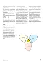
5 The basic physic and technical principles Complete combustion Combustion or burning is a complex sequence of exothermic chemical reactions. A fire starts when a flammable and/or combustible material with an adequate supply of oxygen is exothermically disintegrated. Depending on the speed of combustion, we speak of deflagration, explosion or detonation. A complete combustion causes significant damages, which various with the combustion speed. Order of magnitude of the speed of combustion Deflagration cm/s Explosion m/s Detonation km/s Explosion An explosion can only occur, when three factors...
Open the catalog to page 5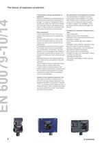
6 The basics of explosion protection Classification of zones and selection of equipment Setting-up installations in potentially explosive areas involves a great deal of precautions to be taken. For instance, the equipment, the resources, the cables and conductors as well as the construction have to meet special requirements. In case of doubt, the consultation of experts during the planning is recommended. Risk assessment It is the responsibility and duty of the user to perform a risk analysis prior to installing new facilities. He must verify where there is a risk of explosion and then divide...
Open the catalog to page 6
7 Classification of the potentially explosive areas into zones To determine the necessary protective measures to be taken and to select appropriate equipment, the potentially explosive areas have to be classified into zones. This classification of the potentially explosive areas into zones is based upon the frequency and the duration of the presence of the dangerous explosive atmosphere. These framework conditions (frequency, duration) determine the classification and identification of gas explosion risk areas as zone 0, 1 or 2 as well as the required measures to be taken in order to avoid active...
Open the catalog to page 7
8 The basics of explosion protection Types of protection General overview Essential requirements The EN 60079-0 describes the essential requirements, which apply to all types of explosion protection. Mechanical protection Mechanical tests are carried out in accordance with EN 60079-0. The enclosures or the exterior part of the enclosure, pushbuttons must withstand highimpact energy. Type of protection „n“ EN 60079-15 The type of protection “n” originally was used as stand-alone standard for use in ATEX category 3G respectively was defined as zone 2 standard in IECEx. This standard has been designed...
Open the catalog to page 8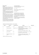
9 Intrinsic safety Principle The type of protection “intrinsic safety” Ex i is based on the principle of limitation of current, voltage and storable energy within an electric circuit. Intrinsic safety does not reduce the potentially explosive substance and/or the oxidizing agent. The ignition of an explosive mixture is avoided, when neither electric sparks nor the effect of heat can occur. The electrical energy is limited in order to keep electrical sparks below the ignition limit. The energy limitation avoids the excessive heating of the electrical apparatus and its surfaces. This also applies...
Open the catalog to page 9
10 The basics of explosion protection Electrical apparatus and associated apparatus An intrinsically safe electric circuit contains at least one electrical apparatus and one associated apparatus. The electric circuits of the electrical apparatus meet the requirements of the intrinsic safety. The electrical apparatus must only be connected to non-intrinsically safe circuits through associated apparatus. An associated apparatus possesses both intrinsically safe and non-intrinsically safe circuits. To separate the electric circuits, a zener diode or galvanic isolators are used. The EN 60079-11 describes...
Open the catalog to page 10
11 In the control cabinet, the intrinsically safe electric circuits must be clearly marked. The standard prescribes no uniform procedure and only points out that for the marking preferably a light blue colour should be used. However, the neutral conductors of energy cables are usually also marked with a blue colour. In order to avoid confusion, another marking should be used for the intrinsically safe electric circuits in this case. What is important, is a conveniently arranged layout and a spatial separation in the control cabinet. Conductive shields must only be earthed at places located outside...
Open the catalog to page 11
12 The basics of explosion protection Mechanical explosion protection The general requirements can be summarised as follows: • The equipment must meet all stipulated application requirements (e.g. rough operation, humidity effects, ambient temperature and pressure fluctuations, influence of chemical agents, corrosion, vibrations) (refer to the operating instructions); • Determination and evaluation of the ignition hazards – Apparatus interior (heating due to failure capable of causing ignition inside the device) – Dust deposits (friction between moving parts) – Evaluation of the surface temperature...
Open the catalog to page 12All SCHMERSAL catalogs and technical brochures
 AS-Interface Safety at Work
36 Pages
 Serial Diagnostics
12 Pages
 Main catalogue Automation technology
146 Pages
 Solenoid Interlock AZM150
4 Pages
 Solenoid interlock AZM201
24 Pages
 Safety interlock AZM40
2 Pages
 Optoelectronic safety devices
28 Pages
 Catalogue Safety Technology
296 Pages
 Innovations 2021/2022
28 Pages
 Product overview
36 Pages


Archived catalogs
 Command and signalling devices
124 Pages
 Packaging industry
28 Pages
 PROTECT SELECT
10 Pages
 Safety light barriers
4 Pages
 ASSB-4P-1M12-V1
2 Pages
 ASSB-2P-1M12-V1
2 Pages
 ASSB-4P-2M12-V1
2 Pages
 ASSB-2P-FKB-V1
2 Pages
 ASSB-4P-SW-V1
2 Pages
 Heavy industry
24 Pages
- Digital imager
- Industrial camera module
- Measuring machine
- Digital I/O
- Infrared imager
- Schmersal single-pole switch
- Schmersal proximity sensor
- IO module
- Junction block
- Schmersal push-button switch
- Hinge
- Terminal box
- Digital IO module
- Schmersal technology switch
- Schmersal cylindrical proximity sensor
- Communication gateway
- Industrial remote control
- Remote control with buttons
- Position transducer
- Inductive proximity sensor