- Catalogs
- Sankyo America
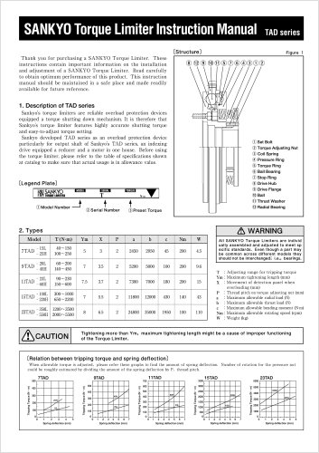
- TAD Alpha Catalog
TAD Alpha Catalog
1 /2Pages
TAD Alpha Catalog
1 /2Pages
All Sankyo America catalogs and technical brochures
 The Zero-Backlash Technology
32 Pages
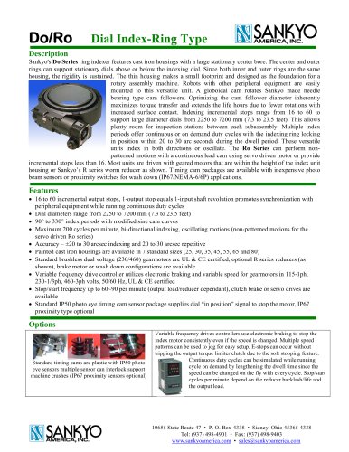 Do Series, Ring Indexer
4 Pages
 Coil Feeds for Presses
23 Pages
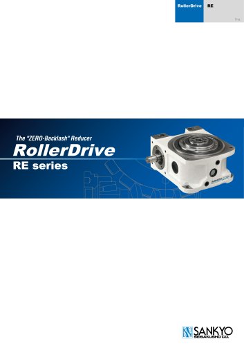 RE Series Catalog
20 Pages
 RA Series Catalog
22 Pages
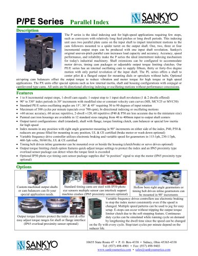 P Series Catalog
2 Pages
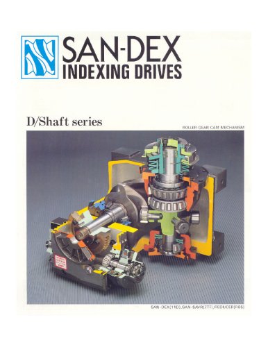 D Series Catalog
24 Pages
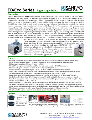 ED Series Catalog
1 Page
 DT/RT/DTR Series Catalog
5 Pages
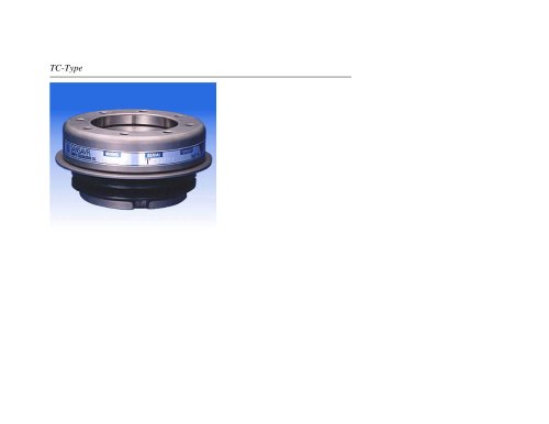 TC Series Catalog
11 Pages
 GY Series Catalog
20 Pages


Archived catalogs
 Eco Series ED Catalog
32 Pages
 Alpha Series Catalog
25 Pages
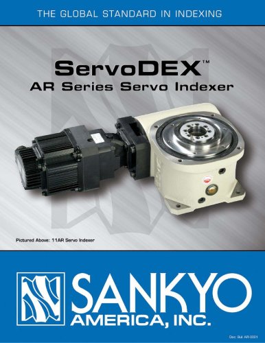 Alpha Servo Catalog
18 Pages
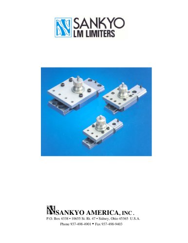 LM Series Catalog
8 Pages
 DF, EF & RF Series Catalog
19 Pages
 D, E & R Series Catalog
18 Pages
Related Searches
- Rail conveyor
- Transport rail conveyor
- Horizontal conveyor
- Feeder
- Turntable
- Chain conveyor
- Electric rotary table
- Horizontal rotary table
- Motor-driven rotary table
- Mounting machine
- Automatic assembling machine
- Overload clutch
- Tool changer
- Index unit
- Vertical rotary table
- Machine tool rotary table
- Cam indexer
- Rotary indexer
- CNC rotary table
- Automatic tool changer
*Prices are pre-tax. They exclude delivery charges and customs duties and do not include additional charges for installation or activation options. Prices are indicative only and may vary by country, with changes to the cost of raw materials and exchange rates.