
Catalog excerpts

ROSTA Motorbases Self-tensioning Motor Mounts for all Friction Belt Drives slippage-free – belt protecting – maintenance-fre
Open the catalog to page 1
Customer Benefits of the ROSTA Offers short-term slippage by the start-up of large inertias, avoiding excessive tension on belt-carcass! Offers fast belt changing, no need of complex readjustment of the pulleys! Fully maintenance-free tensioning system, no need of periodical compensation of belt elongation!
Open the catalog to page 2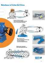
Motorbases in Friction Belt Drives Prevents from slack accruement, avoids heat generating slippage of the belts and averts from premature belt failure! Offers ideal belt tension, constant transmission of nominal torque, less energy consumption, can lead to threefold belt lifetime! MB 70 Noiseless power transmission, all time ideally tightened belt sets!
Open the catalog to page 3
Selection table of ROSTA Motorbases according to the motor frame sizes NEMA Motor Frame Size 143T 145T Motor Frame Size Standard Design Customized designs of motorbases on pages 5.14 – 5.15. For not mentioned motor frame sizes, please
Open the catalog to page 4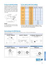
Test forces for ideal belt tensioning Test force table by initial V-belt installation The ROSTA Motorbase is offering with its mechanical pretensioning device the ideal calibration of the relevant belt tension, based on the test force recommendations of the belt suppliers. These recommended test forces for the most common V-belt sizes are mentioned in the test force table on the right. (standard values for the most common types of V-belts) Height [mm] Diam. of smaller pulley [mm] Initial operation test-force FI* [N] V-belt type For screen applications the belt only tighten enough that they...
Open the catalog to page 5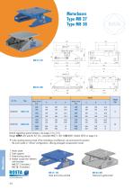
Motorbases Type MB 27 Type MB 38 Motor Frame Size Motor Frame Size Details regarding special designs, see pages 5.14 – 5.15. Design ATEX with specific Art. No., example MB27 × 120: 02300201. Details ATEX on page 5.4. s effectual, we recommend to position * Ithethe resulting tension-travel of the motorbase not enlarged compensation travel. motor plate in “off-set” configuration, offering 1 Motor plate 2 Side supports 3 Pretensioning device 4 Rubber suspension element with brackets (MB 27: 2 brackets / MB 38: 3 brackets)
Open the catalog to page 6
Mounting instructions for MB 27 and MB 38 1 Determine of the ideal motorbase position MB 27 MB 27: 4 slotted holes 11 × 25 mm MB 38: 4 slotted holes 13.5 × 35 mm alter position of pretensioning device 3 Alignment of pulleys and motor fixation 4 Loosen of the shaft bolt (element axis) 4 bolts according to relevant motor size 5 Insert and tension the belts, control belt test force Tensioning of the belts according to belt suppliers recommended test force ( table on page 5.5). MB 27: by means of threaded bushing with 16 mm wrench (M10) MB 38: by means of threaded shaft with 24 mm wrench...
Open the catalog to page 7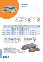
Motor Frame Size Motor Frame Size Details regarding special designs, see pages 5.14 – 5.15. Design ATEX with specific Art. No., example MB50 × 270-1: 02300526. Details ATEX on page 5.4. ROSTA Motorbases MB 50 * Allotor plate installed in “off-set” will be supplied with m configuration. Accord ing to the final positioning of the base, the operating a ngle of the belts and the required tensioning travel, the motor late can be altered in “centered” position on p top of the element axis. Relevant threaded fixation holes are exist nt in plate. e For possibly required higher i nclination...
Open the catalog to page 8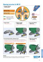
Mounting instructions for MB 50 1 etermine of the ideal D motorbase position Operation area “above” Motor plate standing ~ 30° inclined Operation area “below” Motor plate standing ~ horizontal ideal position of the MB, longest tensioning travel sufficient tensioning travel contact ROSTA 3 Alignment of pulleys and motor fixation 4 bolts according to relevant motor size 5 Insert and tension the belts, control belt test force Tensioning of the belts according to belt suppliers recommended test force. Adjust tension with a 30 mm wrench (M20), uniformly if 2 pretensioning devices are supplied....
Open the catalog to page 9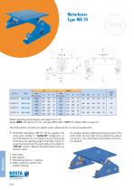
Motor Frame Size Motor Frame Size Details regarding special designs, see pages 5.14 – 5. 5. 1 Design ATEX with specific Art. No., example MB70 × 400: 02300710. Details ATEX on page 5.4. We will be glad to calculate your specific system, please ask for our relevant questionnaire. ROSTA * Allotor late Motorbases MB 70 will be supplied with m p installed in “centered” configuration on top of the element axis. According to the final positioning of the base, the operating angle of the belts and the re quired tensioning travel, the motor plate can be altered in “off-set” position. Relevant...
Open the catalog to page 10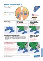
Mounting instructions for MB 70 1 Determine of the ideal motorbase position ideal position of the MB, longest tensioning travel sufficient tensioning travel contact ROSTA Do not use compressed-air power tools for tensioning! 2 Support fixations 4 slotted holes 22 × 54 mm 3 Alignment of pulleys and motor fixation 4 bolts according to relevant motor size 4 Loosen of the center bolts (element axis) and of the bolts on friction plates 46 mm wrench (M30) and 24 mm wrench (M16) 5 Insert and tension the belts, control belt test force Tensioning of the belts according to belt suppliers recommended...
Open the catalog to page 11
Motor Frame Size Motor Frame Size Details regarding special designs, see pages 5.14 – 5.15. Design ATEX with specific Art. No., example MB100 × 750: 02300900. Details ATEX on page 5.4. We will be glad to calculate your specific system, please ask for our relevant questionnaire. travel of * For possibly required longer tensioningthe rubberthe motor L-supports, the pretensioning device (3) shall be bolted into the front holes of the fork-head on suspension element. 1 Motor L-supports 2 Side supports 3 Pretensioning device 4 Rubber suspension element
Open the catalog to page 12All ROSTA catalogs and technical brochures
-
 DO-A
DO-A4 Pages
-
 DK-A
DK-A4 Pages
-
 DR-A
DR-A4 Pages
-
 DK-S
DK-S4 Pages
-
 DR-C
DR-C4 Pages
-
 Product Info Type DR-S
4 Pages
-
 Green Technology
12 Pages
-
 New Motorbase ATEX
8 Pages
-
 Type AB TWIN
7 Pages
-
 Product Group Tensioner Devices
16 Pages
-
 Screen Mounts
20 Pages
-
 Double Suspension Type AD-P
5 Pages
-
 ROSTA Technology
11 Pages
-
 Anti-vibration Mounts
16 Pages
-
 TENSIONER DEVICES
16 Pages
-
 SCREEN MOUNTS
20 Pages
-
 MOTORBASES
16 Pages


