Group: Rohde & Schwarz

Catalog excerpts
Test & Measurement R&S®RTO Digital Oscilloscope Scope of the art
Open the catalog to page 1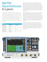
R&S®RTO Digital Oscilloscope At a glance The R&S®RTO oscilloscopes combine excellent s ignal fidelity, high acquisition rate and the world's first realtime digital trigger system with a compact device format in the 600 MHz up to 4 GHz class. They offer hardware-accelerated measurement and analysis functions as well as an advanced user interface that makes these instruments really fun to work with. Models Base unit Despite the wide variety of measurement and nalysis a functions, the oscilloscopes are easy and intuitive to o perate. Flat menu structures and signal flow diagrams...
Open the catalog to page 2
R&S®RTO Digital Oscilloscope Benefits and key features Convincing accuracy ❙❙ Precise measurements due to very low inherent noise ❙❙ High dynamic range due to single-core A/D onverter c ❙❙ Full measurement bandwidth, even for input ensitivity s r anges ≤ 10 mV/div ❙❙ Low gain and offset rrors e ❙❙ High channel-to-channel isolation prevents rosstalk c ▷▷ page 12 Triggering and ecoding of serial protocols d ▷▷ page 14 Power analysis F ind signal faults fast ❙❙ One million waveforms per second: ault finding instead f of guesswork ❙❙ High acquisition rates without limitation...
Open the catalog to page 3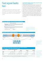
F ind signal faults fast Conventional digital oscilloscopes: long blind time with serious consequences The R&S®RTO oscilloscopes continuously capture and analyze waveforms up to one million times per second. This capability is unique among digital oscilloscopes and helps to find rare signal faults quickly. A digital oscilloscope acquires signals in two steps. First, it samples the measurement signal for a defined period of time and stores the samples. In a second step, it processes these samples and displays the waveform. During this period, the oscilloscope is “blind” to the measurement...
Open the catalog to page 4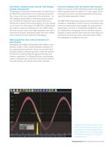
One million waveforms per second: ault finding f instead of guesswork Compared to conventional oscilloscopes, the blind time of the R&S®RTO oscilloscopes is up to twenty times shorter. This is due to the core component of the instrument – an ASIC designed specifically for intensive parallel processing. The ASIC processes the input signal within an extremely short period of time and prepares it for fast display on the screen. For this reason, the R&S®RTO oscilloscopes can acquire, analyze and display up to one million waveforms per second. Due to this high acquisition rate, the instruments...
Open the catalog to page 5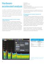
Hardware- accelerated analysis An ASIC in the R&S®RTO oscilloscopes employs 02 fold parallel signal processing which ensures high acquisition rates, even for complex signal nalysis. a The results are available quickly and are based on a large number of waveforms that provide statistically meaningful information. High measurement speed, even for complex analysis functions Standard functions such as mathematical operations, mask tests, histograms, spectrum display and automatic measurements require additional computing time. If they are implemented in software, the blind time increases...
Open the catalog to page 6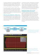
The ability to overlap the FFT means that the R&S®RTO oscilloscopes are also able to correctly display intermittent signals such as pulse-type interferers. Particularly when operating the oscilloscope in persistence mode, users can see what is really happening in the measured signal. As in spectrum analyzers, operation is based on entering the center frequency, span and resolution bandwidth. The numeric grid annotation is particularly user-friendly. Measurements such as total harmonic distortion (THD) and power spectrum density (PSD), which are usually the realm of spectrum analyzers, can...
Open the catalog to page 7
Highly accurate digital trigger system Precise measurements due to low trigger jitter Conventional oscilloscopes use an analog triggering architecture. They divide the analog measurement signal in the frontend, and process it in separate trigger and acquisition paths. However, these different signal paths cause time and amplitude offset. This results in measurement inaccuracies that cannot be completely corrected by postprocessing. Due to the use of hardware-based signal processing, the digital trigger system used in the R&S®RTO oscilloscopes is the first to operate in realtime. It...
Open the catalog to page 8
High trigger sensitivity at full bandwidth The digital trigger can validate every acquired sample against the trigger definition. For this reason, the R&S®RTO oscilloscopes are able to trigger on even the smallest signal amplitudes. In order to achieve stable triggering regardless of signal noise levels, the user can set a trigger hysteresis for the oscilloscopes. And due to the low-noise frontends, the oscilloscopes can also trigger on signals with vertical input sensitivities of < 10 mV/div at full measurement bandwidth. Adjustable digital filter for the trigger signal The digital trigger...
Open the catalog to page 9
New ease of operation The R&S®RTO oscilloscopes unite established c oncepts with new features and turn user wishes into reality: Just unpack the instrument, switch it on – and measure. Straightforward, smart menu structure Different tools for operating the instrument help users to employ the diverse functions quickly and without a lot of searching: ❙❙ All the settings are no more than two clicks away with the clearly structured menus on the bottom edge of the screen ❙❙ Signal flow diagrams in the dialog boxes visualize signal processing; crosslinks lead directly to logically related...
Open the catalog to page 10
Color-coded control elements for clear ser u guidance The controls for the vertical system and the trigger ystem s are color-coded. Multicolor LEDs around the knobs for vertical positioning and scaling visualize the currently selected channel in the appropriate color. The color coding matches the waveform display and the result windows on the screen. The clear allocation enables smooth work, even with complex measurement tasks. Signal icons with drag & drop functionality When working with multiple signals, the screen becomes easily cluttered. This is not the case with the oscilloscopes...
Open the catalog to page 11All Rohde Schwarz catalogs and technical brochures
-
 R&S®FPC Spectrum analyzer
16 Pages
-
 R&S®ZNL vector network analyzer
18 Pages
-
 R&S®MXO 4 Oscilloscope
40 Pages
-
 R&S®RTE1000 oscilloscope
40 Pages
-
 R&S®FPL1000
20 Pages
-
 R&S®ZNA vector network analyzers
52 Pages
-
 R&S®HF907
2 Pages
-
 R&S®RO129 Antenna Rotator
6 Pages
-
 R&S®PR100 Portable Receiver
30 Pages
-
 R&S®ETC Compact TV Analyzer
12 Pages
-
 R&S®RSC Step Attenuator
10 Pages
-
 R&S®RTA4000 Oscilloscope
22 Pages
-
 R&S®NRP Power Meter Family
40 Pages
-
 R&S®EVSF1000
12 Pages
-
 R&S®UMS175
10 Pages
-
 R&S®AVHE100
24 Pages
-
 HM8030
2 Pages
-
 R&S®HMC8015 Power Analyzer
10 Pages
-
 R&S®HM8118 LCR-Bridge
2 Pages
-
 Digital Multimeter HMC8012
3 Pages
-
 Mobile network testing solutions
20 Pages
-
 Value Instruments Catalog
69 Pages
-
 Test & Measurement Catalog 2016
266 Pages
-
 R&S®BBA150 Broadband Amplifier
16 Pages
-
 R&S®UPZ Audio Switcher
6 Pages
-
 R&S®SMZ Frequency Multiplier
8 Pages
-
 Test & Measurement Catalog 2013/2014
214 Pages
-
 R&S®CMW-CU Control Unit
6 Pages
-
 R&S®FSQ Signal Analyzer
14 Pages
-
 R&S®FSU Spectrum Analyzer
16 Pages
-
 R&S®RTE-B1 Mixed Signal, 400 MHz
26 Pages
-
 R&S®ZVB Vector Network Analyzers
20 Pages
-
 R&S®IQR I/Q Data Recorde
16 Pages
-
 R&S®CMA180 Radio Test Set
16 Pages
-
 R&S®CBT/CBT32 Bluetooth® Tester
20 Pages
-
 R&S®UPV Audio Analyzer
24 Pages
-
 R&S®RTE Digital Oscilloscope
26 Pages
-
 R&S®TSMX-PPS2 GPS Module
4 Pages
-
 R&S®CMW500 Platform overview
20 Pages
-
 R&S®EM010 VXI HF Receiver
10 Pages
-
 EMC Precompliance Solutions
79 Pages
-
 UMS120 Monitoring Syste
8 Pages


Archived catalogs
-
 Network Operators Catalog
18 Pages
-
 Broadcasting Catalog
144 Pages
-
 Secure communication Catalog
274 Pages
-
 T & M Product Catalog
146 Pages
-
 R&S®RF Step Attenuators
2 Pages
-
 Q8384 Optical Spectrum Analyzer
10 Pages
-
 R&S®NRP Power Meter
22 Pages
-
 Audio Analyzers ¸UP 300/¸UP 350
16 Pages
-
 R&S®ZVL Vector Network Analyzers
14 Pages
-
 SMU200A Flyer
2 Pages
-
 SMU200A Vector Signal Generator
44 Pages
-
 R&S®EVS300 ILS/VOR Analyzer
12 Pages
-
 WiMAX Communication Tester
16 Pages


