- Catalogs
- RKB Europe
- RKB Guidelines for Mounting Four-Row Cylindrical Roller Bearings Poster
RKB Guidelines for Mounting Four-Row Cylindrical Roller Bearings Poster
1 /1Page

RKB Guidelines for Mounting Four-Row Cylindrical Roller Bearings Poster
1 /1Page
Catalog excerpts
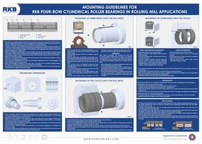
RKB FOUR-ROW CYLINDRICAL ROLLER BEARINGS IN ROLLING MILL APPLICATIONS BEARING INDUSTRIES 1 - Loose flange rings RKB multi-row cylindrical roller bearings are used almost exclusively to support the roll necks of back- up rolls in rolling mill machinery. They are designed with well-balanced cross-sections to provide the highest possible radial load carrying capacity within the bearing envelope. In order to properly meet application requirements, RKB multi-row cylindrical roller bearings are produced in several designs and executions that basically differ in the number of inner and outer rings, in the number of loose or integral flanges on the outer ring, in the cage type, in the number of rollers and related arrangement in cage pocket. Multi-row cylindrical roller bearings can accommodate only radial loads and tolerate moderate to high mill speeds; possible axial loads have to be accommodated by other types of bearings (deep groove ball bearings, angular contact ball bearings, tapered roller bearings, tapered roller thrust bearings, or spherical thrust roller bearings). RKB four-row cylindrical roller bearings are of separable design, which considerably simplifies mounting, inspection and maintenance operations. Both inner rings (designation L) and outer ring assemblies (designation R) are interchangeable, this being helpful for quick roll replacement. Outer ring assemblies, consisting of outer rings, rollers, and cages, can be mounted independently of inner rings, or all bearing components can be mounted separately. The mounting of the bearing onto the roll neck has to be in accordance with the mounting instructions supplied with the rolling mill machinery design. PRELIMINARY OPERATIONS Prior to mounting, measure the chock bore diameter in four equally spaced planes normal to the bore axis of symmetry (a, b, c, d) and in each plane in four directions offset at 45° (1, 2, 3, 4). These measurements have to be properly recorded. Measure the shaft diameter in four planes (or three, according to the neck shape) normal to the shaft axis of symmetry (a, b, c, d) and in each plane in four directions offset at 45° (1, 2, 3, 4). These measurements have to be properly recorded. Bore and shaft shape deviations are highly recommended to be measured as well. Record all these measurements in a measuring report. Properly lubricate bearing components according to the lubricant suggested in the rolling mill machinery design. For easy mounting, be sure that the chock and the shaft are clean and lubricated; this will reduce the wear and corrosion of the assembly elements during operation. MOUNTING OF INNER RINGS ONTO THE ROLL NECK Push the labyrinth ring or backing ring (heated in an oil bath) onto the roll neck until it abuts the roll body face Heat the inner rings in an oil bath or, if available, using an induction coil. When the inner rings are heated in an oil bath, use a thermostatto avoid excessively high heating temperature. Wipe off the oil in the bores and from the faces of the bearing inner rings after they are removed from the oil If the roll neck end is not shaped to guide the inner rings (stepped sections), we highly recommend using a mounting sleeve. In case of small bearings, manually push the inner rings (heated in an oil bath) on the roll neck. In case of large bearings, use mounting grippers, which have to carry the rings always with their axis in a horizontal For inner rings heated using an induction coil, push manually or using an appropriate lifting device the coil together with the bearing inner ring onto the roll neck. After using an induction coil, bearing inner rings and roll necks remain magnetized and have to be properly demagnetized. This can be done by pulling the induction coil itself over the mounted part with the current switched on and slowly removing to a distance of 1-2 meters from the • After cooling down, the rolling bearing inner rings should abut the labyrinth ring without a gap. • Inner rings of smaller bearings can be mounted without a gap between them by pushing a mounting sleeve against the ring face while the rings cool down. • After mounting onto the roll neck,itis highly recommended to measure the raceway diameters of the inner rings carrying out the same procedure for measuring the shaft MOUNTING OF THE CHOCK ONTO THE ROLL NECK Check if the labyrinth ring and the inner rings have been fitted onto the roll neck. Mount the seal neighboring the shaft shoulder onto the chock. Carry in a horizontal position the pre-assembled chock (complete with outer ring assembly and bearings which should take the axial loads) to the roll neck by means of a crane. Align the chock as closely as possible with the roll neck so that the chock can be easily pushed onto the roll neck. Carefully push the pre-assembled chock onto the roll neck so that no score marks are produced on the rollers or inner ring raceways. Mount the axial clamping and the sealing system onto the shaft and make sure that it is properly adjusted and secured. MOUNTING OF OUTER RINGS INTO THE CHOCK LARGE SIZE BEARINGS • Fasten the roll-side cover onto the chock. • Place the chock with its bore axis in horizontal • Be sure that the outer rings have their axis aligned with the chock bore axis. • Insert the rings into the chock using a beam suspended in ropes or cables. SMALL AND MEDIUM SIZE BEARINGS Fasten the roll-side cover onto the chock. Place the chock on level supports with bore axis in vertical position. In case of small bearings, manually insert the outer rings into the chock. In case of medium bearings, insert the outer rings into the chock by means of a special clamping/ lifting device or, when the bearing is provided with threaded holes for eye bolts, by means of ropes, cables or chains attached to the crane hook. On initial mounting, place the outer ring marked zone in the load direction and mark the position on the top Carefully place the desired load zones of the outer rings in the same direction. Make sure that adjacent parts abut each other completely and check the seating of the outer ring against the cover shoulder or loose flange with a feeler gauge. If need be, mount the bearing which should take the axial loads. Dismounting of RKB four-row cylindrical roller bearings from the roll neck encompasses two distinct phases: 1) Withdrawal of the chock from the inner rings • Remove the axial clamping and the sealing system from the roll neck. • Carefully remove the chock from the roll neck as a complete unit. • When only the rolls are replaced, mount the chock onto the new roll neck only after the inner rings have been • Dismount bearing components for inspection in the reverse order of mounting and using the same equipment. 2) Extraction of the inner rings from the roll neck • If the inner rings are mounted with tight fit on the roll neck, use the same induction coil as for mounting. • Quickly heat the inner rings in order to release the tight fit. The RKB new generation four-row cylindrical roller bearings GX type introduce optimized features such as the double window-type cage, the alternate long/short roller arrangement and the inner ring with higher To improve bearing lubrication there are annular grooves and lubrication holes on the outer rings and lubrication grooves in their side faces. The special GX type configuration alternating long and short rollers has been introduced to get a better load distribution and reduce the edge contact pressure typical of standard designs. Another important feature introduced by the RKB GX configuration is the higher chamfer angle and length on the inner ring raceway, specific for each different geometry. The controlled drop of rollers, obtained through the double window-type cage and the new dimension of the inner ring chamfer, permits a quicker and more efficient mounting with a much lower incidence of bearing Standard design: not controlled drop of rollers controlled drop of rollers Technological Bearings
Open the catalog to page 1All RKB Europe catalogs and technical brochures
 Cylindrical rolelr bearings
2 Pages
 Technological bearings
2 Pages
 Project S12
2 Pages
 RKB Product Table
2 Pages
 This Is RKB
24 Pages
 RKB Phosphate Treatment
2 Pages
 RKB General Information Form
12 Pages
 Project "241 KPP VL"
2 Pages
 Project "EPB"
2 Pages
 Project "MDU"
2 Pages
 Project "ABI"
2 Pages
 TQOS Maintenance
3 Pages
 AF2D Multiroll Cage Design
2 Pages
 RKB_Europe_SA_ISO_9001
1 Page
 RKB_Europe_SA_ISO_14001
1 Page
 RKB_Europe_SA_ISO_27001
1 Page
 RKB_Europe_SA_ISO_10002
1 Page
 RKB General Quality Program
50 Pages
 RKB Special Projects
68 Pages
 RKB Metals Industry Leaflet
2 Pages
 RKB Company Snapshot
2 Pages
 RKB Brief Company Profile
2 Pages
 RKB_Taper_Roller_Bearings_Assy
39 Pages
 RKB Bearings Production Range
34 Pages
 RKB Bearings Catalogue
168 Pages
 Made in RKB
1 Page
 RKB Taper Roller Bearings Assy
39 Pages
 Why RKB
1 Page
 RKB Basic Load Ratings
14 Pages
 Bearing Industry Matrix
2 Pages
 RKB_Business_Card_T3
1 Page
 RKB_Business_Card_T2
1 Page
 RKB Message of the President
2 Pages
 RKB Brief Introduction
2 Pages
 RKB Digital Presentation
50 Pages
 Company name and motto
6 Pages