
Catalog excerpts

DRILLNG INSTRUMENTATION Pump Stroke Counter System PUMP STROKE COUNTER SYSTEM Model PSC-3 Instruction Manual …Quality is Everything... This manual describes the installation operation and maintenance of the Model PSC-3 Pump Strokes Counter System. This manual shall provide the user with information necessary to properly utilize the Pump Strokes Counter. Included in this manual are all the necessary procedures to install and maintain this Pump Strokes Counter Instrumentation properly. Email: service@rigchina.com SKYPE:RIGCHINA Website: http://www.rigchina.com Telephone: 0086-579-87537698 Fax: 0086-579-8753 696 Address: No.80-82, Qiude Road, West Cheng Industrial Estate, Yongkang city, Zhejiang P
Open the catalog to page 1
DRILLNG FLUID TESTING INSTRUMENTATION RheoVADR™ Rheometer ©2015 Rigchina Group Company All rights reserved. No part of this work covered by the copyright hereon may be reproduced or copied in any form or by any means (graphic, electronic, or mechanical) without first receiving the written permission
Open the catalog to page 2
DRILLNG FLUID TESTING INSTRUMENTATION RheoVADR™ Rheometer 1. Introduction The Pump StrokeCounter (Model PSC-3) monitors and displays the total accumulated mud pump strokes and the stroke rate of up to 3 individual mud pumps simultaneously. The stroke rate for each mud pump can be individually display and is updated every second. The Battery Pack is designed to operate continuously for 2 years. No calibration is required. The quartz crystal oscillator provides high precision counts with no drift. The Pump StrokeCounter is designed to be intrinsically safe. The stainless steel case is...
Open the catalog to page 3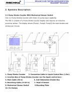
DRILLNG FLUID TESTING INSTRUMENTATION RheoVADR™ Rheometer 2. Systems Description: 2.1 Pump Stroke Counter With Mechanical Sensor Switch One (1) Pump Strokes Counter with three (3) pump input capability. The PSC-3 consists of a Pump Stroke Counter display and requires an inductive proximity sensor. The display shows (Pump1, Pump2, Pump3) the total strokes and strokes per minute. 1. Pump Stroke Counter 2. Connection Cable in Liquid Control Box (1.5m) 3. Junction Box of Pump Stroke Counter (on the liquid control box) 4. Main Cable (50 m) 8. Mechanical Sensor Switch
Open the catalog to page 4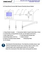
DRILLNG FLUID TESTING INSTRUMENTATION RheoVADR™ Rheometer 2.2 Pump Stroke Counter With Passive Proximity Sensor Switch 1. Pump Stroke Counter 2. Connection Cable in Liquid Control Box (1.5m) 3. Junction Box of Pump Stroke Counter (on the liquid control box) 4. Main Cable (50 m) 8. Passive Proximity Sensor Switch The Inductive Proximity Sensor: The inductive proximity sensor used with the Pump Stroke Counter has a sensing range of 15mm. Care must be taken when mounting the sensor so it can safely detect the movement of the metal mass moving past th
Open the catalog to page 5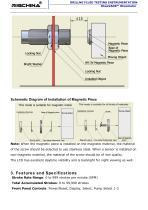
DRILLNG FLUID TESTING INSTRUMENTATION RheoVADR™ Rheometer Schematic Diagram of Installation of Magnetic Piece Note: When the magnetic piece is installed on the magnetic material, the material of the screw should be selected to use stainless steel. When a sensor is installed on non-magnetic material, the material of the screw should be of iron quality. The LCD has excellent daytime visibility and is backlight for night viewing as well. 3. Features and Specifications Stroke Rate Range: 0 to 999 strokes per minute (SPM) Total Accumulated Strokes: 0 to 99,999 strokes Front Panel...
Open the catalog to page 6
DRILLNG FLUID TESTING INSTRUMENTATION RheoVADR™ Rheometer Time Base: Quartz Crystal oscillator Pump Switch Micro-switch or passive proximity sensor Battery: ER26500 3.6V industrial lithium battery Intrinsically Safe sealed Power Pack Battery Life: 2 years continuous operation Maximum Cable Length: 250 ft (80 m) from pump switch to StrokeCounter Dimensions: 8"X8"X3.3" LXWXD (20.3X20.3X8.4 cm) Weight: 6.6 Lbs. (3 Kgs) Case Material: Stainless steel Operating & Storage Temperature: -40 to 100°C 4. Installation The Pump Stroke Counter is mounted in a driller’s or choke control panel in a...
Open the catalog to page 7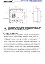
DRILLNG FLUID TESTING INSTRUMENTATION RheoVADR™ Rheometer Care should be taken not to over-tighten these bolts, as the clear panel behind the front panel can fracture if torque sufficient to distort the stainless front panel is applied. 5. Theory of Operation This system is comprised of a Control Head containing the necessary batteries, dis-plays, control and external connector. All power is supplied by a 3.6 Volt battery contained inside the instrument housing. Under normal use this battery should last approximately 2 years. The required input to the Pump Stroke Counter is either a...
Open the catalog to page 8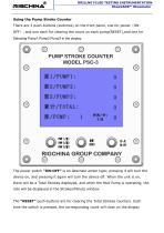
DRILLNG FLUID TESTING INSTRUMENTATION RheoVADR™ Rheometer Using the Pump Stroke Counter There are 3 push-buttons (switches) on the front panel, one for power(ONOFF), and one each for clearing the count on each pump(RESET),and one for Selecting Pump1,Pump2,Pump3 in the display. The power switch “ON-OFF” is an alternate action type; pressing it will turn the device on, and pressing it again will turn the device off. When the unit is on, there will be a Total Strokes displayed, and when the Mud Pump is operating, the rate will be displayed in the Strokes/Minute window. The “RESET”...
Open the catalog to page 9
DRILLNG FLUID TESTING INSTRUMENTATION RheoVADR™ Rheometer 6. Calibration No calibration is required for the Pump Stroke Counter. The device contains an internal crystal clock, which is used for determining the pump stroke rate. 7. Maintenance The internal battery will have to be replaced at the end of its life. This will normally be several years – a normal life is approximately 2 years with 24 hour Operation but the life can be short-ened with extremes of temperature. When the display segments appear to no longer have a high contrast, it is time to replace the battery. Turning the...
Open the catalog to page 10All RIGCHINA GROUP COMPANY catalogs and technical brochures
-
 12 Speed Viscometer
23 Pages
-
 6 Speed Viscometer
23 Pages
-
 Garrett Gas Train
28 Pages
-
 Core Saturator
4 Pages
-
 Mechanical Dynamometer 2016
3 Pages
-
 Deadline Anchors
11 Pages
-
 Weight Indicator systems
11 Pages
-
 PRESSURE GAUGE MODEL 8
5 Pages
-
 MUD PUMP PRESSURE GAUGES
19 Pages
-
 DRILLING INSTRUMENTATION
38 Pages
-
 Oil and Water Retort Kit
19 Pages


