- Products
- Catalogs
- News & Trends
- Exhibitions
RGH25F UHV, RGH20F UHV
1 /8Pages

RGH25F UHV, RGH20F UHV
1 /8Pages
Catalog excerpts
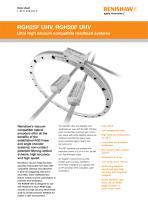
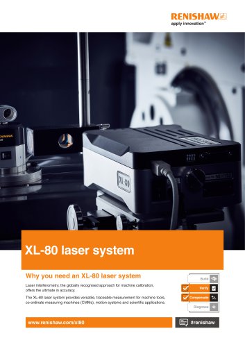
RGH25F UHV, RGH20F UHV Ultra high vacuum compatible readhead systems Renishaw’s vacuum compatible optical encoders offer all the benefits of the established RG2 linear and angle encoder systems; non-contact patented filtering optical scheme, high accuracy and high speed. Renishaw’s vacuum range has been specially constructed from clean UHV compatible materials and adhesives to give low outgassing rates and a clean RGA. These readheads also feature reduced current consumption to minimise heat dissipation. The RGH20F UHV is designed for use with Renishaw’s 20 µm RESR angle encoder and high accuracy RSLR linear scale to provide precision feedback for motion in UHV environments. The RGH20F UHV and RGH25F UHV readheads are used with the REF interface which incorporates automatic gain control and unique self-tuning adaptive electronics. Combined with filtering optics, these ensure excellent signal integrity and low cyclic error. The REF interfaces are available with resolution options of 5 µm to 5 nm, as well as 1 Vpp analogue output. An integral tri-coloured set-up LED enables quick and easy installation. All of these readheads are supplied with an RFI screened UHV compatible cable as standard. • Clean RGA • Low outgassing rates • High bake-out temperature of 120 °C • Low power consumption readheads • Non-contact open optical system • Resolution to 5 nm • Low cyclic error, <50 nm • Self-tuning adaptive electronics give high accuracy and long-term reliability • Reads RGS20-S tape scale, 20 µm RESR angle encoder or RSLR linear scale
Open the catalog to page 1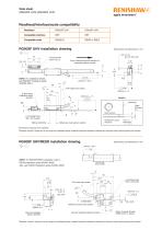
Readhead/interface/scale compatibility Readhead Compatible interface Compatible scale Arrow indicates forward direction of readhead relative to scale NOTE: For installation details, see RGH25F Installation guide (M-9562-0001) >R10 static bend radius 26 A-9541-0037 Reference mark actuator 2 mounting holes M3 x 0.5 through Optical centreline Scale surface Readhead to scale clearance Reference mark sensor position *Dimensions measured from substrate. = Required nominal 0.8 gap can be set using blue readhead spacer (supplied) positioned between readhead and actuator when positioning/fixing the actuator....
Open the catalog to page 2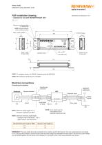
Optional mounting brackets (A-9539-2018) NOTE: Remove washers when installing brackets Input 15 way D type socket Calibrate button Output 15 way D type plug NOTE: For installation details, see RGH25F Installation guide (M-9532-0001) NOTE: REF interfaces are not vacuum compatible Electrical connections Grounding and shielding Feedthrough connector Readhead Vacuum chamber Customer electronics Inner shield (if fitted) PIN 15 NOTE: Inner shield must be connected to 0V at customer electronics only NOTE: Maximum cable length of 5 m betweeen readhead and REF NOTE: Maximum extension cable length: - analogue...
Open the catalog to page 3
Operating and electrical specifications Power supply 5 V - 5% +10% System fully active<300 ms after power applied. Interface and readhead are protected from reverse voltage and over voltage up to 12 V. Renishaw encoder systems must be powered from a 5 V dc supply complying with the requirements for SELV of standard EN (IEC) 60950. 200 mVpp maximum @ frequency up to 500 kHz maximum Current consumption (For digital outputs) (For analogue outputs) Readhead only, 50 mA System, 200mA maximum Current consumption figures refer to unterminated interfaces. A further 25 mA per channel pair (eg A+, A-)...
Open the catalog to page 4
apply innovation " Self-tuning active correction The REF interface actively corrects for input signal imperfections to optimise system accuracy. Corrections are made for the following: Automatic Offset Control (AOC) - adjusts offset independently for the sine and cosine signals Automatic Gain Control (AGC) - ensures consistent 1 Vpp signal amplitude Automatic Balance Control (ABC) - adjusts the gain to equalise the sine and cosine signals These correction mechanisms operate over the full working speed range of the readhead. The user can disable/enable the AGC by pressing the CALIBRATE button...
Open the catalog to page 5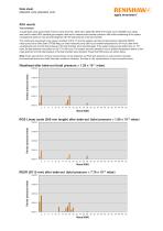
Data sheet apply innovation " Test schedule A quadrupole mass spectrometer (Thermo Onix Smart IQ+ fitted with a triple filter 300D UHV head), set to 250AMU scan range, was used to collect RGA (residual gas analysis) data and to measure total chamber pressure. After initial conditioning of the system, a background spectrum was recorded together with the total pressure in the test chamber. The component was placed in the vacuum chamber (0.015 m3) and the system was then pumped using an Edwards E2M18 rotary pump and a Seiko Seiki STP300 Mag Lev turbo-molecular pump (300 l/s) at ambient temperature...
Open the catalog to page 6
Output specifications Digital output signals - type REF digital output interfaces Analogue output signals - type REF0000 Form - Square wave differential line driver to EIA RS422A Incremental 2 channels A and B in quadrature (90° phase shifted) Incremental 2 channels V1 and V2 differential sinusoids in quadrature (90° phase shifted) Signal period 1 Vpp (nominal) with AGC active Wide reference (option C) Differential pulse I0 -18° to 108°. Duration 126° (electrical) Repeatability of position (uni-directional) maintained within ±10 °C from installation temperature and for speed <250 mm/s Synchronised...
Open the catalog to page 7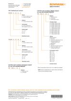
New Mills, Wotton-under-Edge, Gloucestershire GL12 8JR United Kingdom UHV readhead part numbers RGH25F 15 Interface part numbers (digital output) for use with RGH25F/RGH20F C - Vacuum reference mark D - Vacuum limit switch A - Reference mark B - Limit switch C - Wide reference mark Options 01 - Vacuum head and cable Clocked output 50 - 50 MHz customer clock 40 - 40 MHz customer clock 25 - 25 MHz customer clock 20 - 20 MHz customer clock 12 - 12 MHz customer clock 10 - 10 MHz customer clock 08 - 8 MHz customer clock 06 - 6 MHz customer clock 05 - 5 MHz customer clock 03 - 3 MHz customer clock...
Open the catalog to page 8All RENISHAW catalogs and technical brochures
 TP7M probe and stylus kit
4 Pages
 inVia Raman microscope
28 Pages
 Renishaw fixtures
68 Pages
 QC20 ballbar
16 Pages
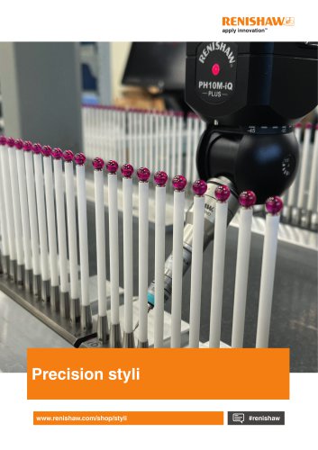 Precision styli brochure
40 Pages
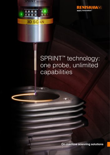 SPRINT technology brochure
11 Pages
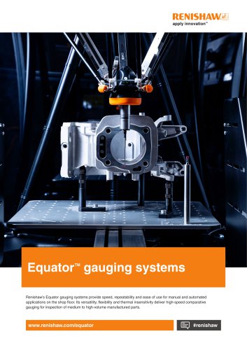 Equator brochure
12 Pages
 Metrology fixture table
4 Pages
 RFP1 fringe probe for REVO-2
2 Pages
 RVP vision probe for REVO-2
2 Pages
 MH20 articulating probe head
2 Pages
 Data sheet: MH20 and MH20i
4 Pages
 RTP20
RTP202 Pages
 PH10M-iQ PLUS
2 Pages
 REVO-2 and RSP2 probes
2 Pages
 SFP2 surface finish probe
2 Pages
 Data sheet: HS20 laser head
2 Pages
 Data sheet: RLU20 laser unit
2 Pages
 Data sheet: RLU10 laser unit
2 Pages
 RLMD01_09
13 Pages
 RLBD01_04
9 Pages
 RLCD03_03
9 Pages
 HiLin™
20 Pages
 PRIMO™ system
8 Pages
 RSP3-6 extended reach probe
4 Pages
 RGH22 series readhead
4 Pages
 Renishaw retrofit
12 Pages
 SP80
SP804 Pages
 SP600
SP6004 Pages
 Styli for Zeiss applications
57 Pages
 Precision styli
60 Pages
 CMM technology guide
28 Pages


- Temperature probe
- RENISHAW rotary encoder
- Measuring machine
- RENISHAW incremental encoder
- Microscope
- Calibration system
- RENISHAW incremental rotary encoder
- Monitoring software solution
- RENISHAW absolute rotary encoder
- Measurement software
- Thermocouple temperature transducer
- Solid-shaft rotary encoder
- Laboratory microscope
- Automated software
- RENISHAW optical rotary encoder
- Programming software
- RENISHAW magnetic rotary encoder
- RENISHAW industrial rotary encoder
- IP67 rotary encoder