- Catalogs
- Reece Safety Products
- BS16 / BS17 Ball Valve Lockouts
BS16 / BS17 Ball Valve Lockouts
1 /1Page

BS16 / BS17 Ball Valve Lockouts
1 /1Page
Catalog excerpts

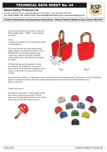
Reece Safety Products Ltd Premier House, Manchester Road, Mossley, Lancashire OL5 9AA Tel: 01457 831133 Fax: 01457 831144 Data sheet No: 20 BS16 / BS17 © Reece Safety Products Ltd 2006 Installation Information As shown in the photo, straddle the ball valve with the two halves of the ball valve lockout. The ball valve handle is captured within the cavity of one of the mating ball valve lockout halves as shown. With the four "legs" of the ball valve lockout pointing as shown, insert the mating halves together as shown. NOTE: on pipes upto 40mm dia the device will also secure the valve handle in a position parallel to the pipe (locked open). Push the two mating halves together tightly and apply a padlock by inserting the lock shackle through the two mating holes that are aligned with one another. After applying the padlock, VERIFY that the ball valve lockout device has properly secured the valve handle - a) attempt to remove the lockout device, b) try and move the handle. If either attempt is successful, re-apply the device. If the construction of the ball valve is such that this ball valve lockout cannot secure the handle, DO NOT USE. CAUTION: This lockout device is designed to prevent inadvertent or unintentional activation of the valve to which it is attached. If you cannot verify that the device is securely attached. DO NOT USE NOTE: An insert channel is provided to accommodate a large variety of valve handle dimensions with a snug fit. The insert is designed to ensure a snug fit of levers however on some applications it may be necessary to remove it.
Open the catalog to page 1All Reece Safety Products catalogs and technical brochures
 Power Protection Seal
2 Pages
 60kV Rescue Hook
1 Page
 ELE09 Switchboard Matting
4 Pages
 Lockable plug covers
1 Page
 Plug Block
1 Page
 Full 2015/16 Catalogue
100 Pages
 Electrical Safety Boots
1 Page
 Electrical Safety Gloves
1 Page
 RSPL1 Plug Lockout
1 Page
 ECBKIT MCB Lockout Kit
2 Pages
 Pneumatic Lockouts
1 Page
 Plug Lockouts
1 Page
 BS18 Cable Lockout
1 Page
 CB15 Breaker Blocker Kit
1 Page
 Fuse Lock / Blockouts
1 Page
 IEC 60320 Lockout
1 Page
 LP550 Plug Lockouts
1 Page
 Power Protection Seal
2 Pages