- Catalogs
- Reece Safety Products
- BS11 Pneumatic, BS12 Cable lockout
BS11 Pneumatic, BS12 Cable lockout
1 /1Page

BS11 Pneumatic, BS12 Cable lockout
1 /1Page
Catalog excerpts

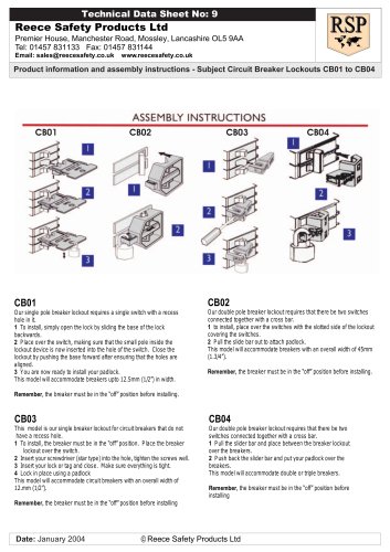
Reece Safety Products Ltd Premier House, Manchester Road, Mossley, Lancashire OL5 9AA Tel: 01457 831133 Fax: 01457 831144 Email: [email protected] www.reecesafety.co.uk Product information and assembly instructions - Subject Pneumatic Lockout Technical Data Sheet No: 7 1 Insert male air fitting into appropriate Lockout entry (Fig. 1) 2 Three fitting types can be accomodated. 3 Insert lock to secure male air fitting into Lockout device (Fig. 2) Caution: Ensure male air fitting cannot be removed with a padlock in place. Note: Two lock sizes can be used per Lockout opening. (Fig. 3) Date: January 2004 © Reece Safety Products Ltd WARNING!! ! All associated hazardous energy should be verified as de-energized prior to and following the installation of a Lockout device. ! Appropriate use of the Lockout product is the sole responsibility of the user in relation to compliance of employers and current Health and Safety Regulations. 1 Route cable system through all associates devices intended to be Locked out. 2 Insert cable system through Lockout system body. 3 Pull cable system tight Product information and assembly instructions - Subject Cable Lockout 6.35mm 7.14mm diameter holes 4 Compress trigger to lock cable in place. 5 Insert lock through hole to secure trigger in locked position. 6 The system is now locked out.
Open the catalog to page 1All Reece Safety Products catalogs and technical brochures
 Power Protection Seal
2 Pages
 60kV Rescue Hook
1 Page
 ELE09 Switchboard Matting
4 Pages
 Lockable plug covers
1 Page
 Plug Block
1 Page
 Full 2015/16 Catalogue
100 Pages
 Electrical Safety Boots
1 Page
 Electrical Safety Gloves
1 Page
 RSPL1 Plug Lockout
1 Page
 ECBKIT MCB Lockout Kit
2 Pages
 Pneumatic Lockouts
1 Page
 Plug Lockouts
1 Page
 BS18 Cable Lockout
1 Page
 CB15 Breaker Blocker Kit
1 Page
 Fuse Lock / Blockouts
1 Page
 IEC 60320 Lockout
1 Page
 LP550 Plug Lockouts
1 Page
 Power Protection Seal
2 Pages