- Catalogs
- Quality Transmission Components
- Surface Strength 0f Spur And Helical Gears
Surface Strength 0f Spur And Helical Gears
1 /7Pages

Surface Strength 0f Spur And Helical Gears
1 /7Pages
Catalog excerpts
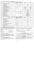
17.1.11 Example of Bending Strength Calculation Table 17-8A Bending Strength Factors No. Item Symbol Unit Pinion Gear 1 Normal Module mn mm 2 2 Normal Pressure Angle an degree 20º 3 Helix Angle b 0º 4 Number of Teeth z 20 40 5 Center Distance ax mm 60 6 Coefficient of Profile Shift x +0.15 -0.15 7 Pitch Circle Diameter d mm 40.000 80.000 8 Working Pitch Circle Diameter dw 40.000 80.000 9 Tooth Width b 20 20 10 Precision Grade JIS 5 JIS 5 11 Manufacturing Method Hobbing 12 Surface Roughness 12.5 mm 13 Revolutions per Minute n rpm 1500 750 14 Linear Speed v m/s 3.142 15 Direction of Load Unidictional 16 Duty Cycle Cycles Over 107 cycles 17 Material SCM 415 18 Heat Treatment Carburizing 19 Surface Hardness HV 600 ...640 20 Core Hardness HB 260 ... 280 21 Effective Carburized Depth mm 0.3 ... 0.5 Table 17-8B Bending Strength Factors No. Item Symbol Unit Pinion Gear 1 Allowable Bending Stress at Root sFlim kgf/mm² 42.5 2 Normal Module mn mm 2 3 Tooth Width b 20 4 Tooth Profile Factor YF 2.568 2.535 5 Load Distribution Factor Ye 0.619 6 Helix Angle Factor Yb 1.0 7 Life Factor KL 1.0 8 Dimension Factor of Root Stress KFX 1.0 9 Dynamic Load Factor KV 1.4 10 Overload Factor KO 1.0 11 Safety Factor SF 1.2 12 Allowable Tangential Force on Working Pitch Circle Ftlim kgf 636.5 644.8 17.2 Surface Strength Of Spur And Helical Gears The following equations can be applied to both spur and helical gears, including double helical and internal gears, used in power transmission. The general range of application is: Module: Pitch Circle: Linear Speed: Rotating Speed: mdv n 1 .5 to 25 mm 25 to 3200 mm less than 25 m/sec less than 3600 rpm 17.2.1 Conversion Formulas To rate gears, the required transmitted power and torques must be converted to tooth forces. The same conversion formulas, Equations (17-1), (17-2) and (17-3), of SECTION 17 are applicable to surface strength calculations. 17.2.2 Surface Strength Equations As stated in SECTION 17.1. the tangential force. Ft, is not to exceed the allowable tangential force, Ftlim The same is true for the allowable Hertz surface stress, sHlim The Hertz stress sH is calculated from the tangential force, Ft For an acceptable design, it must be less than the allowable Hertz stress sHlim That is: sH £ sHlim (17-12) The tangential force, Ftlim, in kgf, at the standard pitch circle, can be calculated from Equation(17-13). The Hertz stress sH (kgf/mm²) is calculated from Equation (17-14). where u is the ratio of numbers of teeth in the gear pair. The "+" symbol in Equations (17-13) and (17-14) applies to two external gears in mesh, whereas the "-" symbol is used for an internal gear and an external gear mesh. For the case of a rack and gear, the quantity u/(u±1) becomes 1. 405
Open the catalog to page 1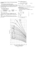
7.2.3 Determination of Factors In the Surface Strength Equations 17.2.3.A Effective Tooth Width, bH(mm) The narrower face width of the meshed gear pair is assumed to be the effective width for surface strength. However, if there are tooth modifications, such as chamfer, tip relief or crowning, an appropriate amount should be substracted to obtain the effective tooth width. 17.2.3.B Zone Factor, ZH The zone factor is defined as: (17-15) where: bb = tan-1(tanb cosat) The zone factors are presented in Figure 17-2 for tooth profiles per JIS B 1701, specified in terms of profile shift coefficients...
Open the catalog to page 2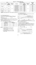
Table 17-9 Material Factor, Zm Gear Meshing Gears Material Factor ZM (kgf/mm²)0.5 Material Symbol E Young's Modulus kgf/mm² Poison's Ratio Material Symbol E Young's Modulus kgf/mm² Poisson's Ratio Structural Steel * 21000 0.3 Structural Steel * 21000 0.3 60.6 Cast Steel SC 20500 60.2 Ductile Cast Iron FCD 17600 57.9 Gray Cast Iron FC 12000 51.7 Cast Steel SC 20500 Cast Steel SC 20500 59.9 Ductile Cast Iron FCD 17600 57.6 Gray Cast Iron FC 12000 51.5 Ductile Cast Iron FCD 17600 Ductile Cast Iron FCD 17600 55.5 Gray Cast Iron FC 12000 50.0 Gray Cast Iron FC 12000 Gray Cast Iron FC 12000 45.8 *...
Open the catalog to page 3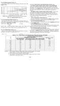
17.2.9 Sliding Speed Factor, Zv This factor relates to the linear speed of the pitch line. See Figure 17-5. 17.2.10 Hardness Ratio Factor, Zw The hardness ratio factor applies only to the gear that is in mesh with a pinion which is quenched and ground. The ratio is calculated by Equation (17-20). Zw = 1.2 - HB2 - 130 (17-20) 1700 where: HB2 = Brinell hardness of gear range: 130 £ HB2 £ 470 If a gear is out of this range, the Zw is assumed to be 1.0. 17.2.11 Dimension Factor, KHX Because the conditions affecting this parameter are often unknown, the factor is usually set at 1.0. KHX = 1.0 (17-21)...
Open the catalog to page 4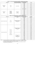
Table 17-13 Gears with Induction Hardening - Allowable Hertz Stress Material Heat Treatment before Induction Hardening Surface Hardeness HV (Quenched) s H lim Structural Carbon Steel S43C S48C Normalized 420 77 440 80 460 82 480 85 500 87 520 90 540 92 560 93.5 580 95 600 and above 96 Structural Alloy Steel SMn443 SCM435 SCM440 SNC836 SNCM439 Quenched and Tempered 500 109 520 112 540 115 560 117 580 119 600 121 620 123 640 124 660 125 680 and above 126 Table 17-14 Carburized Gears- Allowable Hertz Stress Material Effective Carburized Depth Surface Hardeness HV (Quenched) s H lim kgf/mm² Structural...
Open the catalog to page 6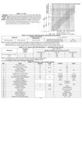
Table 17-14A Module 1.5 2 3 4 5 6 8 10 15 20 25 Depth, mm A 0.2 0.2 0.3 0.4 0.5 0.6 0.7 0.9 1.2 1.5 1.8 B 0.3 0.3 0.5 0.7 0.8 0.9 1.1 1.4 2.0 2.5 3.4 NOTE:For two gears with large numbers of teeth in mesh, the maximum shear stress point occurs in the inner part of the tooth beyond the carburized depth. In such a case, a larger safety factor, SH, should be used. Table 17-15 Gears with Nitriding- Allowable Hertz Stress Material Surface Hardness (Refrence) s H lim kgf/mm² Nitriding Steel SAC 645 etc. Over HV 650 Standard Processing Time 120 Extra Long Processing Time 130...140 Note: In order to...
Open the catalog to page 7All Quality Transmission Components catalogs and technical brochures
 KSUW1.5-R1
1 Page
 KKRCPFD10-1000J
1 Page
 KSAM1.5-20045
1 Page
 KSH2-20R
1 Page
 KSS0.5-30C
1 Page
 DIAMETRAL PITCH GEAR
34 Pages
 Q420 Catalog
526 Pages
 TOOTH THICKNESS
16 Pages
 SPUR GEAR CALCULATIONS
5 Pages
 Introduction to Metric Gears
15 Pages
 DESIGN OF PLASTIC GEARS
15 Pages
 WORM GEARING
5 Pages
 BEVEL GEARING
6 Pages
 HELICAL GEARS
6 Pages
 INTERNAL GEARS
4 Pages


- Compact gearhead
- Bevel gearhead
- Rack and pinion
- Straight-toothed sprocket wheel
- Straight-toothed gear
- Helical gear rack
- Metal gear
- Metal sprocket wheel
- Helical-toothed gear
- Spur gear
- Bevel gear
- Straight-toothed rack and pinion
- Steel gear
- Hub gear
- Ground rack and pinion
- Plastic gear
- Ratchet wrench
- Shaft gear
- Cylindrical gear
- Steel rack and pinion