- Catalogs
- OMS Motion, Inc.
- MAXv Specifications
MAXv Specifications
1 /88Pages

MAXv Specifications
1 /88Pages
Catalog excerpts

USER’S MANUAL INTELLIGENT MOTION CONTROLLERS For VME and VME64 bus MAXv FAMILY OMS Motion, Inc. 15201 NW Greenbrier Parkway B-1 Ridgeview BEAVERTON, OR 97006 PHONE 503-629-8081 FAX 503-629-0688 EMAIL: [email protected]
Open the catalog to page 1
COPYRIGHT NOTICE © 2013 OMS Motion, Inc. This document is copyrighted by OMS Motion, Inc. You may not reproduce, transmit, transcribe, store in a retrieval system, or translate into any language in any form or by any means, electronic, mechanical, magnetic, optical, chemical, manual, or otherwise, any part of this publication without the express written permission of OMS Motion, Inc. TRADEMARKS IBM, IBM PC, IBM PC/XT, IBM PC/AT, IBM PS/2, and IBM PC DOS are registered trademarks of International Business Machines Corporation. CompactCPCI, PICMG-PCI, PICMG are registered trademarks of the PCI...
Open the catalog to page 2
MAXv User’s Manual I
Open the catalog to page 3
A. LIMITED WARRANTY B. TECHNICAL INFORMATION / RETURN FOR REPAIR PROCEDURES C. SPECIFICATIONS INDEX 2H MAXv User’s Manual
Open the catalog to page 4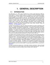
GENERAL DESCRIPTION The OMS Motion, Inc. MAXv motion controllers form a family of high performance VME busbased products and are in compliance with the universal 6U VME Bus Specification ISO/IEC 15776 (2001 E). The MAXv motion controller can manage up to 8 axes of open-loop stepper, closed-loop stepper or servo systems, in any combination at the user’s option, as incremental encoder feedback can be provided on each axis. The OMS MAXv controller synchronizes all independent or coordinated motion of up to 8 axes, while incorporating other critical signals, such as hard or soft limits, home, and...
Open the catalog to page 5
SYSTEM OVERVIEW GENERAL DESCRIPTION SYSTEM OVERVIEW The MAXv is a standard length size 6U VME module (6.299 x 9.187 Inches) that can be installed in a VME cage, see Figure 2-5. The MAXv communication interface is accessed through the VME Bus via the J1/J2 connectors and is compliant with the VME Bus Specifications ISO/IEC 15776 (2001 E) 8H The MAXv utilizes an optimally configured Power PC RISC based 32-bit micro-controller and FPGA technology for extensive logic integration and flexibility. The MAXv motion controller has three high density front panel SCSI connectors. The IOvMAX is the companion...
Open the catalog to page 6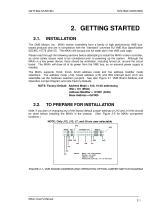
GETTING STARTED SYSTEM OVERVIEW The OMS Motion, Inc. MAXv motion controllers form a family of high performance VME busbased products and are in compliance with the “Standard” universal 6U VME Bus Specification ISO/IEC 15776 (2001 E). The MAXv will occupy one full width slot in the VME card cage. Please read through the following sections before attempting to install the MAXv motion controller, as some safety issues need to be considered prior to powering up the system. Although the MAXv is a low power device, there should be ventilation, including forced air, around the circuit board. The MAXv...
Open the catalog to page 7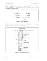
SYSTEM OVERVIEW GETTING STARTED J12 contains the IRQ and the address mode selection jumpers. The IRQ interrupt level range is 0x010-0x111 (IRQ2-7) and the default setting is 0x101 (IRQ5). The address mode selection supports the 16-bit, 24-bit, or 32-bit address space operation. Note that an open jumper indicates a “1” bit and a closed jumper is a “0”. J13 contains the hardware address modifier and the board’s main address selection jumpers. Note that not all combinations of address modifiers are valid. Please refer to the VMEbus specification and/or the user manual for your processor card. Default...
Open the catalog to page 8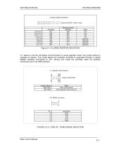
GETTING STARTED SYSTEM OVERVIEW J13 Base Address Selection Default (0xF000 in Short mode) FIGURE 2-5 J11 AND JP1, DEBUG MODE SELECTION MAXv User’s Manual
Open the catalog to page 9
SYSTEM OVERVIEW GETTING STARTED J12 = IRQ and Address Mode J13 = Address and Address Modifier J8 = P2 Step or Servo Selection 9.187 J11 = Debug mode Selection FIGURE 2-6 MAXVPCB DIAGRAM NOTE: The J2 Backplane connector interface signals are selected on J8 as Shown in Figure 2-6. J8 routes signals to the J2 connector if they need to be controlled from the VME. All analog and digital signals are accessible via the three front panel connectors (J3, J4 and J5). Most signal are also accessible via the VME 160-pin back plane connector. Further routing of signals to the back J2 connection is done with...
Open the catalog to page 10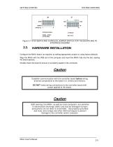
GETTING STARTED SYSTEM OVERVIEW Figure 2-7 STEP/SERVO AND IO/ANALOG JUMPER SWITCH FOR THE BACKPLANE P2 INTERFACE DIAGRAM HARDWARE INSTALLATION Configure the MAXv board, as required, by setting appropriate jumpers or using factory defaults. Align the MAXv with the VME slot of the computer and insert the MAXv fully into the slot, seating the board ejectors. Double check the board to ensure it is properly seated in the connector. Caution Establish communication with the controller board before wiring external components to the board (i.e. drivers and motors ). DO NOT make wiring connections to the...
Open the catalog to page 11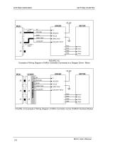
SYSTEM OVERVIEW GETTING STARTED 5V GROUND STEP DIRECTION AUXILIARY Vi GROUND PULSE DIRECTION AUXILIARY INPUT PHA+ PHAPHB+ FIGURE 2-8 Example of Wiring Diagram of MAXv Controller Connected to a Stepper Driver / Motor TERMINAL BLOCK STEP DIRECTION AUXILIARY Vi GROUND PULSE DIRECTION AUXILIARY INPUT PHA+ PHAPHB+ PHB- FIGURE 2-9 Example of Wiring Diagram of MAXv Controller via the IOvMAX Interface Module MAXv User’s Manual
Open the catalog to page 12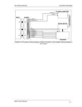
GETTING STARTED SYSTEM OVERVIEW Analog Input TERMINAL BLOCK Analog Ground SERVO MOTOR 5V Ground X PHASE +A X PHASE -A X PHASE +B X PHASE -B X INDEX + X INDEX - FIGURE 2-10 Example of Wiring Diagram of MAXv Controller via the IOvMAX Interface Module to Servo Motor MAXv User’s Manual
Open the catalog to page 13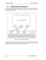
SYSTEM OVERVIEW GETTING STARTED IOVMAX BREAKOUT MODULE The IOvMAX breakout module is an accessory for the MAXv family. It provides an easy way to set all the control and I/O signals and provides a screw terminal connection for each signal. A block diagram is shown below. MAXv (Component Side) Figure 2-11 IOvMAX Break-Out to MAXv The IOvMAX provides 180 screw terminals, one for each signal from the IOvMAX to the MAXv controller. The 100-pin connector on the IOvMAX is pin compatible with the VME58 controller. Details for the IOvMAX break out module are shown in Chapter 4. MAXv User’s Manual
Open the catalog to page 14All OMS Motion, Inc. catalogs and technical brochures
 General Product Catalog
25 Pages
 MAXnet 10-Axis
4 Pages
 PC78
PC784 Pages
 MAXv
MAXv4 Pages
 UMX-USB
4 Pages
 PC78/104 Bus
10 Pages
 IODnet Interconnect Module
3 Pages
 MAXnet Motion Controller
4 Pages

- Electrical cable
- Data connector
- Polymer connector
- Industrial connector
- Electrical data cable
- Cable connector
- Cable assembly
- Motor controller
- Armored cable
- Crimp connector
- Armored electrical cable
- DC motor controller
- Stepper motor controller
- Nylon connector
- Motor driver
- Multi-axis positioning controller
- Compact motor controller
- Flexible electrical cable assembly
- Ethernet positioning controller