- Catalogs
- CURTISS-WRIGHT
- JC150 Single Axis Joystick Controller
- Company
- Products
- Catalogs
- News & Trends
- Exhibitions
JC150 Single Axis Joystick Controller
1 /16Pages

JC150 Single Axis Joystick Controller
1 /16Pages
Catalog excerpts

JC150 SINGLE AXIS JOYSTICK CONTROLLER Innovation In Motion
Open the catalog to page 1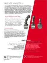
INNOVATION IN MOTION The JC150 single-axis joystick controller is designed for demanding operator control applications in off-highway vehicles and other man-machine interfaces, where lever strength, signal reliability, and handle functionality are important. The joystick is supplied with a long life conductive plastic potentiometer track and directional/center off or end switches to provide signals for sensing lever direction and fault detection. The JC150’s compact size, high lever strength and superb proportional control are ideal for applications which include operator controls on a wide range...
Open the catalog to page 2
JOYSTICK CONTROLLER Total reliability The JC150 includes lever mechanics designed to give smooth proportional control, and has been designed to withstand a load on the handle up to 300N, measured 135mm above the panel. Conductive plastic potentiometer tracks featuring multi-fingered precious metal wipers give low electrical noise and a working life greater than 2 million operations with zero maintenance during this period. Safety Designed to interface with an electronic controller, the long-life potentiometer track generates analog outputs with switched reference signals that are proportional...
Open the catalog to page 3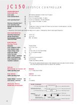
PERFORMANCE MECHANICAL Lever action Lever breakout force* Lever operating force** Maximum allowable force* Lever operating angle Expected life (operations) Weight Self centering (standard) or friction lock (FL option) 4.9 to 10.7 (standard) 13 to 17 to overcome detent - FL option 16.8 to 21.5 (Standard - full lever deflection) 8 to 12 when out of detent - FL option 300 ±34 Greater than 2 million (0.5 million for Friction Lock (FL) action or handle options CL and EL) 560 without handle fitted Measured at 75mm above upper flange face (80mm for FL option) ** Measured at 135mm above upper flange...
Open the catalog to page 4
Note: drawings not to scale 82.5 INSTALLATION The joystick is designed to be fitted from 44mm diameter hole. The effectiveness 2 x 2 holes 13.0mm deep to suit M5 threadform screws. Holes to suit M5 Choose one screw hole each side of centre. of the joystick flange sealing is dependent on the panel mounting surface being sufficiently rigid to compress the sealing 34º gaiter. The surface finish of the mounting Black eggshell epoxy finish on all surfaces. Panel mounting details panel is critical to achieving an adequate seal and rough surface finishes, paint chips, deep scratches, etc. should be...
Open the catalog to page 5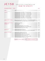
PERFORMANCE OPTIONS axes| | TRACKS LEVER SPRING FORCE HANDLE/GRIP STYLE See pages 7-15 INTERFACE SPECIAL OPTIONS JOYSTICK CONTROLLER HOW TO SPECIFY FEATURE CODE Single Y Analog potentiometer - 5k, 0-100%, ±7.5° directional switch E Analog potentiometer - 10k, 0-100%, ±7.5° directional switch L Analog potentiometer - 1.6k, 0-100%, ±7.5° directional switch N Analog potentiometer - 2.9k, 25-75%, ±5° directional switch Q Analog potentiometer - 2k, 10-90%, ±5° directional switch R Analog potentiometer - 2k, 10-90%, ±7.5° directional switch S Analog potentiometer...
Open the catalog to page 6
JOYSTICK CONTROLLER HANDLE OPTIONS The HKN handle is the simplest option available for the JC150. This handle does not include any additional functionality, but is designed to allow the JC150 joystick to be controlled by the operator gripping the handle, palm downwards. Developed to improve the integrity of your control system, the Center Lock (CL) and End Lock (EL) handles provide a mechanical safety lock – eliminating unwanted movement of the lever. They mechanically hold the shaft of the JC150 in its safe central position or at either end of the JC150’s range of travel. Lifting the collar...
Open the catalog to page 7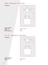
HKN HANDLE OPTION DIMENSIONS ø35 SPECIFICATION Handle material Gloss finish duroplast Handle retention force CL/EL HANDLE OPTION DIMENSIONS SPECIFICATION Handle material Neoprene rubber
Open the catalog to page 8
HB HANDLE OPTIONS NO LONGER AVAILABLE PAGE LEFT INTENTIONALLY BLANK
Open the catalog to page 9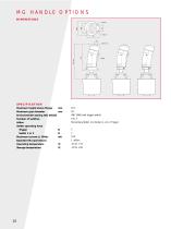
SPECIFICATION Maximum height above flange mm Maximum grip diameter mm Environmental sealing (IEC 60529) Number of switches Action Switch operating force Trigger N Maximum current @ 30Vdc mA Expected life (operations) Operating temperature °C Storage temperature °C
Open the catalog to page 10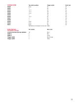
Trigger switch No No No Yes Yes Yes No No Yes Yes No Yes Hand rest No No No No Yes Yes Yes Yes No Yes Yes No See electrical connections for wire color codes. ELECTRICAL Pin number CONNECTIONS Common terminal (for top switches) 16 Switch 1 6 Wire color Black Blue Green Blue/Orange Yellow
Open the catalog to page 11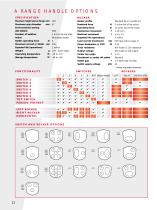
SPECIFICATION Maximum height above flange mm Maximum grip diameter mm Environmental sealing (IEC 60529) Number of switches Action Switch operating force N Maximum current @ 50Vdc mA Expected life (operations) Weight g Operating temperature °C Storage temperature °C ROCKER Rocker profile Breakout force N Operating force N Mechanical movement ° Electrical movement ° Expected life (operations) Load current (maximum) mA Power dissipation @ 25°C W Track resistance Output voltage Center tap angle ° Directional or center off switch Switch gap ° Switch supply voltage...
Open the catalog to page 12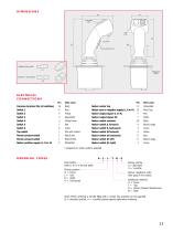
Standard rocker profile Optional V - rocker profile ELECTRICAL CONNECTIONS Wire color Black Blue Yellow Blue/White White/Green Red Violet Pink with marker Red/Green Black/White White/Red Person present switch t Person present switch t Rocker positive supply (L, R or H) 2 Rocker zero or negative supply (L, R or H) 15 Rocker output signal (L or H) 7 Rocker output signal (R) 7 Rocker switch common 16 Rocker switch (L forward) 4 Rocker switch (L backward) 3 Rocker switch (R forward) 5 Rocker switch (R backward) 6 Rocker switch (H left) 6 Rocker switch (H...
Open the catalog to page 13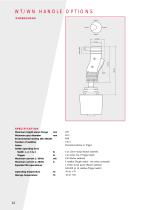
SPECIFICATION Maximum height above flange mm Maximum grip diameter mm Environmental sealing (IEC 60529) Number of switches Action Switch operating force Switch 1, 2, 3 & 4 N Trigger N Maximum current @ 30Vdc mA Maximum current @ 28Vdc A Expected life (operations) Operating temperature Storage temperature 190 40.5 IP66 0 to 5 Momentary Rocker or Trigger 5 at 11mm radius (Rocker switches) 3 at center line of Trigger switch 100 (Rocker switches) 5 resistive (Trigger switch - two wires connected) 1 million at full power (Rocker switches) 500,000 @ 1A resistive (Trigger switch) -40...
Open the catalog to page 14All CURTISS-WRIGHT catalogs and technical brochures
 S-Drive
2 Pages
 AES-350
18 Pages
 AES-349
25 Pages
 Industrial Division
8 Pages
 Transmission Shifter
2 Pages
 SBW
SBW3 Pages
 newVSI Brochure
2 Pages
 Multi-Function Grip
2 Pages
 SCM100
3 Pages
 wm-67
wm-672 Pages
 wm-672
2 Pages
 wm-674
1 Page
 wm-68a
2 Pages
 wm-762
2 Pages
 wm-763
2 Pages
 wm-764
2 Pages
 WM-777
2 Pages
 WM-782
3 Pages
 WM-783
3 Pages
 WM 784
2 Pages
 wm-80
wm-802 Pages
 WCS-133284
5 Pages
 WM 81
WM 812 Pages
 WCS-134143
5 Pages
 Tilt Position Sensor
4 Pages
 Industrial Group
4 Pages
 Sealed Tilt Sensor STT280
2 Pages
 Sealed Tilt Sensor STT500
2 Pages
 Aerial Work Platforms
4 Pages
 AES-204
13 Pages
 ML1951
1 Page
 ML1441 AC
1 Page
 Diagnostic Test Tool
2 Pages
 WM526
WM5262 Pages
 CW-IG-Overview Brochure
8 Pages
 JC050
JC0502 Pages
 JC040
JC0402 Pages
 WM547 Rotary hand control
2 Pages
 WM535 Lever hand control
2 Pages
 C7 Hydraulic Lever
2 Pages
 C6 Hydraulic Lever
2 Pages
 RF15 Series
2 Pages
 RF11 Series
2 Pages
 PGFM3000 Series
3 Pages
 PGF8000 Series
4 Pages
 PGF7000
1 Page
 PGF3000 Series
4 Pages
 CW-IG-Overview
8 Pages
 CW-IG-On-Highway
4 Pages
 CW-IG-Medical Mobility
4 Pages
 CW-IG-Industrial
4 Pages
 CW-IG-Construction
4 Pages
 PGFX3000 Series
2 Pages
 PGFM8000 SERIES
4 Pages
 On-Highway
4 Pages
 GK1037
1 Page
 GK0730
1 Page
 Permanent Magnet
1 Page
 GD1444
1 Page
 D-Frame Solenoid
1 Page
 CW-IG-Agriculture
4 Pages
 SRH220DR
2 Pages
 STT280
2 Pages
 CW-IG-Material Handling
4 Pages
 C3-CE AC Motor Controller
2 Pages
 C3-36V - AC Motor Controller
2 Pages
 WM531 Remote sensor control
2 Pages
 WM526 Electronic floor pedal
2 Pages
 WM537 Electronic floor pedal
2 Pages
 WM558 Electronic floor pedal
2 Pages
 SRS Sealed Rotary Sensors
8 Pages
 STT series Sealed Tilt Sensors
12 Pages
 Holding Magnets
2 Pages
 Digital Panel Indicators
8 Pages


Archived catalogs
 ICS100 IN-CYLINDER SENSORS
8 Pages
- Technology switch
- Position transducer
- Linear position transmitter
- Motor controller
- Control pedal
- Displacement transducer
- Single pedal pedal
- Rotary electric switch
- Linear displacement sensor
- Electronic pedal
- Solenoid
- Analog position transducer
- IP67 switch
- No-contact position sensor
- DC motor controller
- Magnetic position sensor
- Manual potentiometer
- Analog displacement transducer
- Industrial position sensor