Catalog excerpts

Diagnostic testing of instrument transformers
Open the catalog to page 1
Ensure high quality and efficiency during the whole life cycle of your Acting as the link between the primary and secondary system, instrument transformers (IT) are essential for a reliable and safe energy supply. IT testing is of great importance as it helps to; ensure high quality in the production process, accurately install and commission the devices, and operate them within the specifications. In order to make the production process more efficient and to ensure good IT quality and performance, measurements should be performed during the whole life cycle of the devices. Typical IT...
Open the catalog to page 2
instrument transformers Testing and corrective measures > During the production process Determine the exact condition and performance data at defined stages within the production process in order to avoid processing of inaccurate or faulty devices and thus increasing efficiency of production process > After manufacturing Know the actual performance of an IT according to the standards and provide useful fingerprint tests for further comparison > After transport Perform tests after transportation to ensure that the transport didn't cause any mechanical failures in the IT and that it still...
Open the catalog to page 3
Instrument transformer components and detectable faults Component Detectable faults Partial discharges Moisture in paper insulation Aging, moisture, contamination of insulation fluids Defects in the capacitive layers of the potential grading Short circuits (interturn shorts) Open circuits Contact problems Mechanical deformation; Floating core ground; Loose clamping structure Magnetic short circuits Pre-magnetization / residual magnetism Capacitive voltage divider Partial breakdown of single capacitive layers Compensation reactor (CVTs only) Shorted turns Accuracy (ratio error and phase...
Open the catalog to page 4
Possible measurement methods ■ ■
Open the catalog to page 5
The ideal testing solution for your individual needs and requirements Accuracy (ratio error and phase displacement) Ratio / Ratio error Excitation characteristics Winding resistance Partial discharge analysis Dielectric (frequency) response analysis Power factor/dissipation factor measurement: at 50 Hz or 60 Hz with variable frequency Accuracy limit factor (ALF) and terminal voltage (Vb) Residual magnetism measurement Can measure CT and VT ratio CPC 100 can test the ratio of CTs and VTs; tests with higher amplitudes require CP TD12/15 and current booster Only possible for CTs Additional...
Open the catalog to page 6
Multi-functional test set for a comprehensive condition diagnosis and condition assessment of multiple high-voltage assets. Power/dissipation factor and capacitance test set, (including source and reference capacitor) for various highvoltage assets. Portable primary and secondary injection and basic protection test set. Lightweight test set for fast and reliable moisture content determination of oil-paper insulated instrument transformers. Universal partial discharge (PD) measurement and analysis system Ultra-precise test set for dissipation/ power factor and capacitance measurements on...
Open the catalog to page 7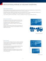
Electrical testing methods on instrument transformers Direct electrical testing Signals (voltage/current) are injected into the primary (HV) side of ITs and the corresponding value is measured at the secondary (LV) side. The determined parameters are ratio, accuracy, polarity, etc. During accuracy tests, different test burdens need to be connected to the IT in order to consider their influence on its behavior. The method can be applied to both conventional and non-conventional ITs. A test with this method at rated voltages / currents is mandatory for every IT as part of the routine tests....
Open the catalog to page 8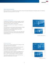
Indirect electrical testing With this method, an IT is tested from the secondary side with test signals differing from the primary values. The method is applicable to conventional ITs (CTs, VTs, CVTs). Secondary voltage injection A dedicated test method for CTs where a voltage is injected via the secondary side. The test voltage is equivalent to the operating terminal voltage at rated burden. The measured excitation curve complies to international standards. The composite error can be determined by applying a voltage according to the CT’s individual operational condition, measuring the...
Open the catalog to page 9
Accuracy (according to IEC/IEEE standards) Why measure? What can be tested? Insulation ü Windings Core Capacitive voltage divider Compensation reactor ü Whole electromagnetic circuit Burden The measurement helps to guarantee a safe, stable and economic energy supply by evaluating the integrity of an IT. With the accurate performance of the IT under test, the operator can obtain an exact image of the system’s voltages and currents. Inductive current and voltage transformers (CT and VT) and capacitive voltage transformers (CVT) can develop ratio and phase deviations. An IT operation using...
Open the catalog to page 10
Good to know ... Only the model-based approach considers and simulates the influence of different burdens and operating ranges on the transformer’s accuracy. The accuracy measurement can also be performed using the primary injection method with connected burden. Other conventional test methods use high currents or high voltages. Why use CT Analyzer / VOTANO 100? >> Provides all relevant information for mobile testing and calibration of protection and metering ITs >> Only existing measurement method using low and comparably safe test signals The model-based accuracy measurements can also be...
Open the catalog to page 11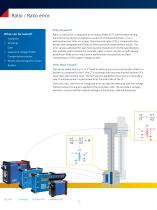
Ratio / Ratio error Why measure? What can be tested? Insulation ü Windings Core ü Capacitive voltage divider Compensation reactor Ratio, or ratio error, is measured as a functional test of ITs' performance during manufacturing, factory acceptance, as part of commissioning tests, or as a performance test after an outage. The measured ratio of ITs is compared to the design and nameplate specifications and to previous measurement results. The error can be calculated for each testing point. Deviations from the specifications may indicate internal faults (for example, open or short circuits) or...
Open the catalog to page 12All OMICRON electronics catalogs and technical brochures
-
 Primary Test ManagerTM
16 Pages
-
 MCT 085
2 Pages
-
 PDL 650
8 Pages
-
 CPC 100
44 Pages
-
 OMICRON Products and Solutions
25 Pages
-
 InSight
4 Pages
-
 MONTESTO 200
16 Pages
-
 ISIO 200
8 Pages
-
 CMControl R
12 Pages
-
 CMControl P
8 Pages
-
 CMS 356
2 Pages
-
 IEDScout
8 Pages
-
 Bode 100 - Technical Data
4 Pages
-
 CMA 156
1 Pages