- Catalogs
- OMICRON electronics
- Bode 100 - Technical Data
- Company
- Products
- Catalogs
- News & Trends
- Exhibitions
Bode 100 - Technical Data
1 /4Pages
Bode 100 - Technical Data
1 /4Pages
Catalog excerpts

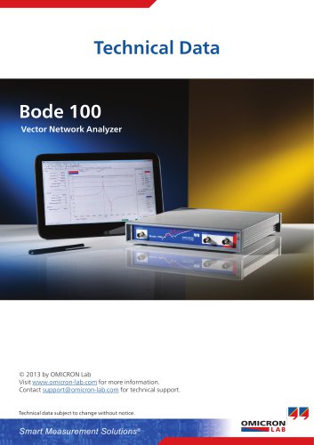
Technical Data Bode 100 Vector Network Analyzer © 2013 by OMICRON Lab Visit www.omicron-lab.com for more information. Contact [email protected] for technical support. Technical data subject to change without notice. Smart Measurement Solutions®
Open the catalog to page 1
1. Signal Source Waveform Sinusoidal signal Frequency range Signal level Accuracy of the source level (23°C ± 5°C) Frequency response of the source level (1Hz to 40MHz) -27 dBm to 13 dBm 0.01 VRMS to 1 VRMS (at 50 Ω load) ± 0.3 dB (1 Hz to 1 MHz) ± 0.6 dB (1 MHz to 40 MHz) ± 0.3 dB (referred to 100 kHz) ± 15 ppm (< 1 year after calibration) ± 25 ppm (< 3 years after calibration) Source impedance: Spurious signals 2. Inputs: CH1, CH2 Input impedance (high) Return loss for low input impedance (1Hz to 40MHz) Receiver bandwidth Noise oor (gain measurement) Conditions: Receiver bandwidth = 10 Hz,...
Open the catalog to page 2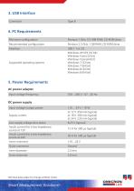
4. PC Requirements Minimum conguration Pentium 1 GHz, 512 MB RAM, CD-ROM drive Recommended conguration Pentium 2.5 GHz, 1 GB RAM, CD-ROM drive Supported operating systems Windows XP SP3 (32 bit) Windows Vista (32 bit) Windows Vista (64 bit) Windows 7 (32 bit) Windows 7 (64 bit) Windows 8 (32 bit) Windows 8 (64 bit) 5. Power Requirements AC power adapter Input voltage/frequency DC power supply Input voltage/output power Supply current at 12 V: 450 mA (typical) at 18 V: 300 mA (typical) at 24 V: 230 mA (typical) Low supply voltage shut-down Inrush current for a low impedance source at 12V Inrush...
Open the catalog to page 3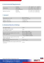
6. Environmental Requirements Temperature Relative humidity Storage Operating For specications Storage Operating Weight - Accessories 8. Absolute Maximum Ratings DC supply voltage DC supply reverse voltage (device doesn’t work) Maximum AC input signals at CH1 or CH2 (high impedance) 50 VRMS up to 1 MHz 30 VRMS 1 MHz to 2 MHz 15 VRMS 2 MHz to 5 MHz 10 VRMS 5 MHz to 10 MHz 7 VRMS 10 MHz to 40 MHz Maximum DC input signal at CH1 or CH2 (high impedance) Maximum input power at CH1 or CH2 (low impedance) Maximum possible return power at the source connector Technical data subject to change without notice....
Open the catalog to page 4All OMICRON electronics catalogs and technical brochures
 Primary Test ManagerTM
16 Pages
 MCT 085
2 Pages
 PDL 650
8 Pages
 CPC 100
44 Pages
 OMICRON Products and Solutions
25 Pages
 InSight
4 Pages
 MONTESTO 200
16 Pages
 ISIO 200
8 Pages
 CMControl R
12 Pages
 CMControl P
8 Pages
 CMS 356
2 Pages
 IEDScout
8 Pages
 CMA 156
1 Page


- Transformer
- ERLO measuring instrument
- ERLO management software
- Automation software solution
- Dry transformer
- Analysis software solution
- ERLO measuring system
- Digital I/O
- Process software
- ERLO Windows software
- Automatic analyser
- IO module
- ERLO calibrator
- Benchtop analyser
- Analog I/O
- ERLO portable tester
- Digital IO module
- Capacitor
- Warning light
- Industrial software