How to use a 3-phase line reactor for a single-phase application
1 /2Pages

How to use a 3-phase line reactor for a single-phase application
1 /2Pages
All MTE catalogs and technical brochures
 Noise Suppression Network
2 Pages
 Guard-AC? PLUS
2 Pages
 RFI and EMI Filters
2 Pages
 Matrix PureSine ®
2 Pages
 RL Line/Load Reactors
2 Pages
 RLW Reactors
2 Pages

Archived catalogs
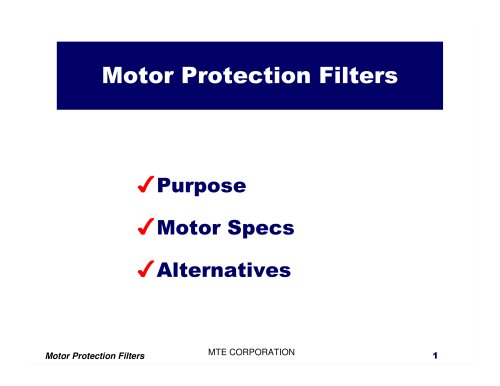
 Motor Protection Filters
2 Pages
 Harmonic Filters
4 Pages
 RFI / EMI Filter Tutorial
17 Pages
 Line Reactor Tutorial
15 Pages
 Load Reactor Tutorial
13 Pages
 Motor Protection Filter Tutorial
11 Pages
 Harmonic Filter Tutorial
36 Pages
 Matrix Filters®
2 Pages
 DC Link Chokes
2 Pages
 MTE Corporation - Catalog
9 Pages


*Prices are pre-tax. They exclude delivery charges and customs duties and do not include additional charges for installation or activation options. Prices are indicative only and may vary by country, with changes to the cost of raw materials and exchange rates.