Group: NOV National Oilwell Varco

Catalog excerpts
SERVICE MANUAL
Open the catalog to page 1
The first six numbers and letters identify the pumps basic design characteristics. In the first space, a number identifies the number of stages in the pumping elements. This will generally be a 1 or 2. The second position, the letter ғB, designates the pump type as being close-coupled. In the third position, a letter designates the pumpԒs drive train (con rod/gear joint/drive shaft): A One size smaller than element (175/220 only) B ֖ Same size as element C Same size as element, but larger gearbox drive flange and drive shaft size (175/220/345 only)The next three positions, always numbers,...
Open the catalog to page 3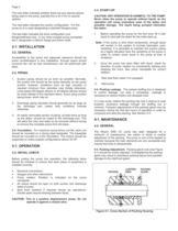
Page 2 The next letter indicates whether there are any special options being used in the pump, typically this is an A for no special options. The next letter indicates the suction configuration. For this pump an A is used designating a standard flanged pump. The last letter indicates the drive configuration and flange/shaft/seal size. In our close coupled pump nameplate the C designates a 250mm flange and 45mm shaft. > CAUTION: DRY OPERATION IS HARMFUL TO THE PUMP! Never allow the pump to operate without liquid, as dry operation will cause premature wear of the stator and possible damage....
Open the catalog to page 4
When packing is new, frequent minor adjustments during the first few hours of operation are recommended in order to compress and seat the packing. 1. Upon initial start-up of the pump, adjust the gland nuts for a leakage rate of 50-100 drops per minute until the packing has seated and adjusted to the operating temperature (approximately 10-15 minutes). 2. If leakage is excessive after 15 minutes of operation, tighten the gland nuts of a turn. 3. Tighten the gland nuts ܼ of a turn after an additional 15 minutes if necessary and repeat this procedure until a desired leakage of 1-2 drops per...
Open the catalog to page 5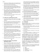
Page 6 2. Gently push the stationary portion of the mechanical seal into the recess in the seal housing (140). Place the O-ring (530) on the shoulder of the seal housing. 3. Slide the seal housing into the drive adaptor (10). Secure the suction housing (100) to the drive adapter (10) with four hex head screws and lock washers (20/30). Take care to be sure the o-ring (530) is placed on the seal housing (140) before assembling. 4. Next, carefully slide the rotating/stator assembly first through the suction housing (100) and then through the seal stationary face in the seal housing and over...
Open the catalog to page 8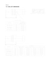
Page 12 13-1. SEAL SET DIMENSIONS >
Open the catalog to page 14
Page 13 14-1. TROUBLESHOOTING CHART >
Open the catalog to page 15
2005 by Moyno, Inc. Printed in U.S.A. ɮMoyno is a registered trademark of Moyno, Inc. >
Open the catalog to page 16All Moyno catalogs and technical brochures
-
 Hygienic Pump
2 Pages
-
 EZstrip Cake Pump
2 Pages
-
 SERIES A
2 Pages
-
 EZstrip™ Hose Pump
16 Pages
-
 Dosing pump
2 Pages
-
 Hygienic Pump
2 Pages
-
 Mine Dewatering
2 Pages
-
 InviziQ™
2 Pages
-
 EZstrip™ TR Muncher
2 Pages
-
 L-Frame
2 Pages
-
 EZstrip? Transfer Pump
2 Pages
-
 Epsilon/Vertical
2 Pages
-
 2000 Pumps
2 Pages
-
 Compact C
2 Pages
-
 Small Pumps
2 Pages
-
 Moyno 1000 Pumps Bulletin
2 Pages
-
 Moyno 500 Pumps Bulletin
2 Pages
-
 Water/Wastewater Brochure
8 Pages
-
 Moyno 1000 Brochure
6 Pages

Archived catalogs
-
 EZstrip™ Cake Pump
2 Pages
-
 Moyno 500 Pumps Selection
4 Pages
-
 Moyno 500 Pumps Brochure
6 Pages
-
 Moyno Metering Pumps Specs
4 Pages
-
 Moyno Grinders Specs
2 Pages
-
 Moyno Grinders Brochure
8 Pages
-
 Moyno 2000 CC Brochure
8 Pages
-
 Moyno 1000 Service Manual
34 Pages


