- Catalogs
- Motion Index Drives, Inc.
- RT Series Rotary Index Table
RT Series Rotary Index Table
1 /14Pages

RT Series Rotary Index Table
1 /14Pages
Catalog excerpts
RT Series Rotary Indexer
Open the catalog to page 1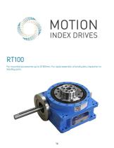
Fixed Index Drives The rotary index table transforms a constant input drive motion into an intermittent output drive motion. The intermittent drive motion occurs by means of a hardened and high accuracy barrel cam. The use of mathematical laws of motion guarantees a soft, shock-proof, and jerk free movement that has been optimally designed for its intended purpose. The design allows for accurate and secure mounting to the output dial. The preload of the cam to the cam followers in dwell ensures the top dial is backlash free. No additional adjustment of the output dial is necessary. Programmable...
Open the catalog to page 2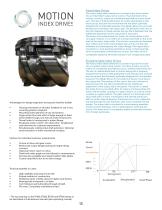
RT400 Technical specifications Main dimensions Overall height (output flange screw-on surface) [mm] 316 Recommended max. size of rotating plate 0 [mm] 3500 Index table weight [kg] 325 Other numbers on request Standard drives Index precision In radian measure on cam follower 0 [mm] ±0.017 In angular seconds on cam follower 0 [“] ±18 Axial runout on cam follower 0 [mm] °.01 Load on output flange Reinforced version Load on central column Direction clockwise, counterclockwise, oscillating *All RT Series tables available in fixed or programmable formats. * The precision is 5 - 8 angular seconds greater...
Open the catalog to page 3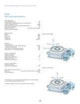
RT400 Dimensions A = Length of input shaft B = Length of shaft to collar C = Diameter of input shaft D = Height of central column to supporting surface on output flange The dimensions shown here are the standard dimensions. The output flange, central column, housing and input shafts can be machined to your specifications. The central column can also be designed as a flange. Should you wish to drill additional holes, please consult us with regard to acceptable drilling depth. Ø550f7 Ø460h11 Ø270h6 Ø110h8 Flange Option The dimensions for the gearmotor may change based on the gearmotor size and...
Open the catalog to page 4
J = Mass moment of inertia in Kgm2 t = Mechanical index time in seconds (does not include dwell) All RT Series tables available in servo programmable versions. *For mounted accessories up to 0 3500mm. Applications in assembly facilities with large and heavy parts: welding, riveting, assembling, and printing/labeling.
Open the catalog to page 5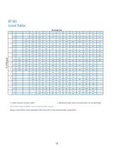
Technical Specifications Main dimensions Overall height (output flange screw-on surface) [mm] 420 Recommended max. size of rotating plate 0 [mm] 4500 Index table weight [kg] 600 Other numbers on request Standard drives Index precision In radian measure on cam follower 0 [mm] ±0.018 In angular seconds on cam follower 0 [“] ±15 Axial runout on cam follower 0 [mm] °.01 Load on output flange Reinforced version Load on central column Direction clockwise, counterclockwise, oscillating All RT Series tables available in fixed or programmable formats. * The precision is 5 - 8 angular seconds greater at...
Open the catalog to page 6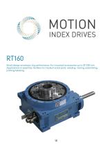
RT500 Dimensions The dimensions shown here are the standard dimensions. The output flange, central column, housing and input shafts can be machined to your specifications. The central column can also be designed as a flange. Should you wish to drill additional holes, please consult us with regard to acceptable drilling depth. A = Length of input shaft B = Length of shaft to collar C = Diameter of input shaft D = Height of central column to supporting surface on output flange Flange Option Central Column increased (Option) 124.8 The dimensions for the gearmotor may change based on the gearmotor...
Open the catalog to page 7
J = Mass moment of inertia in Kgm2 t = Mechanical index time in seconds (does not include dwell) All RT Series tables available in servo programmable versions. *For mounted accessories up to 0 4500mm. Applications in assembly facilities with large and heavy parts: welding, riveting, assembling, and printing/labeling.
Open the catalog to page 8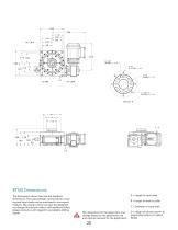
Technical specifications Main dimensions Overall height (output flange screw-on surface) [mm] 560 Recommended max. size of rotating plate 0 [mm] 6000 Index table weight [kg] 1600 Other numbers on request Standard drives All RT Series tables available in fixed or programmable formats. Load on output flange Load on central column * The precision is 5 - 8 angular seconds greater at 16 or more indexes due to multiple dwell on the drive cam. * If required, higher accuracy can be achieved upon request. Index precision In radian measure on cam follower 0 [mm] ±0.023 In angular seconds on cam follower...
Open the catalog to page 9
RT630 Dimensions The dimensions shown here are the standard dimensions. The output flange, central column, housing and input shafts can be machined to your specifications. The central column can also be designed as a flange. Should you wish to drill additional holes, please consult us with regard to acceptable drilling depth. A = Length of input shaft B = Length of shaft to collar C = Diameter of input shaft D = Height of central column to supporting surface on output flange Ø410h7 Ø300 Central Column increased (Option) The dimensions for the gearmotor may change based on the gearmotor size and...
Open the catalog to page 10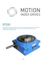
J = Mass moment of inertia in Kgm2 t = Mechanical index time in seconds (does not include dwell) All RT Series tables available in servo programmable versions. *For mounted accessories up to 0 6000mm. Applications in assembly facilities with large and heavy parts: welding, riveting, assembling, and printing/labeling.
Open the catalog to page 11
Technical specifications Main dimensions Overall height (output flange screw-on surface) [mm] 611 Recommended max. size of rotating plate 0 [mm] 9500 Index table weight [kg] 2230 Other numbers on request Standard drives Index precision In radian measure on cam follower 0 [mm] N/A In angular seconds on cam follower 0 [“] N/A Axial runout on cam follower 0 [mm] Load on output flange Load on central column Direction clockwise, counterclockwise, oscillating *All RT Series tables available in fixed or programmable formats. * The precision is 5 - 8 angular seconds greater at 16 or more indexes due...
Open the catalog to page 12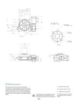
RT900 Dimensions The dimensions shown here are the standard dimensions. The output flange, central column, housing and input shafts can be machined to your speci-fications. The central column can also be designed as a flange. Should you wish to drill additional holes, please consult us with regard to acceptable drilling depth. *For mounted accessories up to Ø 9500mm. Applications in assembly facilities with large and heavy parts: welding, riveting, assembly, and printing/labeling. The dimensions for the gearmotor may change based on the gearmotor size and options required for the ap
Open the catalog to page 13All Motion Index Drives, Inc. catalogs and technical brochures
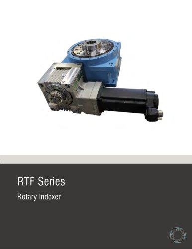 RTF Rotary Index Tables
13 Pages
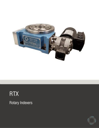 RTX Rotary Index Tables
20 Pages
 TSR Series
13 Pages
 TT315 Series
7 Pages
 Precision Link Conveyor
12 Pages
 Weld Positioner
5 Pages
 TMF Series Rotary Index Table
15 Pages
 XP Series
23 Pages
 Pick and Place
5 Pages
 Product Catalog
152 Pages
 MX150 Slip Ring Brochure
2 Pages
 MX470 Slip Ring Brochure
3 Pages
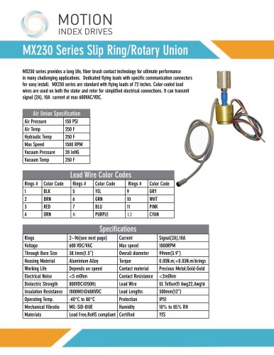 MX230 Slip Ring Brochure
2 Pages
- Rail conveyor
- Transport rail conveyor
- Horizontal conveyor
- Rotary joint
- Multi-port rotary union
- Electric drive conveyor
- Chain conveyor
- Work conveyor
- Oil rotary distributor
- Positioner
- Feed conveyor
- Transfer conveyor
- Conveyor for the pharmaceutical industry
- Mobile conveyor
- Flexible conveyor
- Rotary indexing table
- Assembly line conveyor
- Electric positioner
- Pick-and-place machine
- Electric rotary indexing table