Group: Miki Pulley

Catalog excerpts
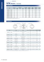
Metal Disc Couplings SFM Models Clamping Specifications Misalignment Parallel [mm] Torsional stiffness [N•m/rad] * Torsional stiffness values given are calculated for the element alone. * The moment of inertia and mass are measured for the maximum bore diameter. * Nominal diameter of clamping bolt M1/M2 is given as number of bolts - nominal diameter, and the number is the number for one hub.
Open the catalog to page 1
Standard Bore Diameter Nominal diameter SPEED CHANGERS & REDUCERS INVERTERS LINEAR SHAFT DRIVES TORQUE LIMITERS ELECTROMAGNETIC CLUTCHES & BRAKES SERIES Metal Disc Couplings SERVOFLEX High-rigidity Couplings * The bore diameters marked with ● are supported as standard bore diameter. Metal Couplings Balance correction Supported rotational speed [min - 1] Model (size) Balance classification Metal Slit Couplings HELI-CAL Metal Coil Spring Couplings BAUMANNFLEX Pin Bushing Couplings Link Couplings Dual Rubber Couplings * We will perform balance correction for supported rotational speeds marked...
Open the catalog to page 2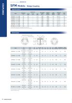
Metal Disc Couplings SFM Models Wedge Coupling Specifications Model Torsional stiffness [N•m/rad] * Torsional stiffness values given are calculated for the element alone. * The moment of inertia and mass are measured for the maximum bore diameter. Detachment screw hole M2 H D L N1・N 2 LF S C K H M 1 Qty - M1 Tightening M 2 Qty [mm][mm] [mm] [mm][mm][mm][mm][mm] Nominal dia. torque [N・m] Nominal dia.
Open the catalog to page 3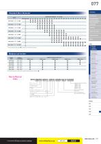
Standard Bore Diameter ELECTROMAGNETIC CLUTCHES & BRAKES SPEED CHANGERS & REDUCERS INVERTERS LINEAR SHAFT DRIVES TORQUE LIMITERS Metal Disc * The bore diameters marked with ● are supported as standard bore diameter. SERVOFLEX High-rigidity Couplings Balance correction Balance classification Metal Couplings Supported rotational speed [min - 1] Model (size) HELI-CAL Metal Coil Spring Couplings BAUMANNFLEX Pin Bushing Couplings Metal Slit * We will perform balance correction for supported rotational speeds marked with ● . Link Couplings SCHMIDT Dual Rubber Couplings Supported rotational speed...
Open the catalog to page 4
Metal Disc Couplings SFM Models Items Checked for Design Purposes ■ Special Items to Take Note of You should note the following to prevent any problems. Surface processed simultaneously with the inner diameter (1) Always be careful of parallel, angular, and axial misalignment. (2) Always tighten bolts with the specified torque. ■ Precautions for Handling Couplings are assembled at high accuracy using a special mounting jig to ensure accurate concentricity of left and right internal diameters. Take extra precautions when handling couplings, should strong shocks be given on couplings, it may...
Open the catalog to page 5
079 ■ Mounting (Wedge Coupling) (9) eep the width of the dimension between flange faces (S K (1) heck that coupling pressure bolts have been loosened and C remove any rust, dust, oil residue, etc. from the inner diameter surfaces of the shaft and couplings. In particular, never allow oil or grease containing antifriction or other agent (molybdenum-, silicon-, or fluorine-based), which would dramatically affect the misalignment with respect to the reference value. Note that the tolerance values were calculated based on the assumption that both the level of parallel misalignment and angular...
Open the catalog to page 6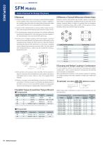
Metal Disc Couplings SFM Models Items Checked for Design Purposes ■ Removal ■ Differences in Torsional Stiffness due to Element Shape (1) heck to confirm that there is no torque or axial load being applied C Elements used by SFM models may be either square or hexagonal. to the coupling. There may be cases where a torque is applied to Since torque is transmitted by coupling the hubs to each other via the the coupling, particularly when the safety brake is being used. Make element, torsional stiffness is higher in couplings that use hexagonal sure to verify that this is not occurring before...
Open the catalog to page 7
(1) ind the torque, Ta, applied to the coupling using the output F capacity, P, of the driver and the usage rotation speed, n. CLUTCHES & BRAKES SPEED CHANGERS (2) etermine the factor K from the load properties, and find the D corrected torque, Td, applied to the coupling. TdNm TaNm× K(Refer to the table below for values) Constant & REDUCERS INVERTERS LINEAR SHAFT DRIVES Vibrations: Small Vibrations: Medium Vibrations: Large TORQUE LIMITERS Load properties For servo motor drive, multiply the maximum torque, Ts, by the usage factor K = 1.2 to 1.5. SERIES Metal Disc TdNm TsNm×3 〜 3.6 (3) et...
Open the catalog to page 8All Miki Pulley Europe AG catalogs and technical brochures
-
 STK Catalog
2 Pages
-
 BXR-LE Model datasheet
2 Pages
-
 Servoflex SFR series
4 Pages
-
 TT(03) Model datasheet
3 Pages
-
 BXL-N datasheet
1 Pages
-
 ASK Model datasheet
1 Pages
-
 ASK Model
2 Pages
-
 BXW Model datasheets
4 Pages
-
 TT Torque Tender
10 Pages
-
 SFS Model
14 Pages
-
 SFC Model
12 Pages
-
 PSL - G Model
2 Pages
-
 Sprflex / Jaw Type
3 Pages
-
 Paraflex Pin Bush
4 Pages
-
 Posi Lock / Klemmelemente
18 Pages
-
 Spring-Actuated Brakes
34 Pages
-
 Power Supplies Brakes
26 Pages
-
 Electromagnetic clutch and brake
14 Pages
-
 Clutch and Brake Units
50 Pages
-
 SFF Model
14 Pages
-
 SFH Model
8 Pages
-
 DC Motors
12 Pages
-
 Speed change Pulley
20 Pages
-
 Baumannflex Models
8 Pages
-
 Starflex ALS Model
16 Pages
-
 KSK Model
2 Pages
-
 BXR-LE Model
2 Pages
-
 BXR Model
4 Pages
-
 BXW Model
4 Pages
-
 BXH Model
4 Pages
-
 BXL Model
4 Pages
-
 BXL-N Model
2 Pages
-
 SFF Model datasheets
9 Pages
-
 SFH Model datasheets
6 Pages
-
 SFM Model datasheets
4 Pages
-
 SFS Model datasheets
21 Pages
-
 Paraflex CPE, CPU
2 Pages
-
 CHP Model datasheet
1 Pages
-
 BXR Model datasheet
2 Pages
-
 BXH Model datasheet
2 Pages
-
 BXL Model datasheet
2 Pages
-
 102, 112, CYT datasheets
8 Pages
-
 121, 122, 125 datasheets
3 Pages
-
 SFC Model Datasheet
6 Pages
-
 TT(01) Model datasheet
3 Pages
-
 KSK Model datasheet
1 Pages
-
 STK Model datasheet
1 Pages
-
 DMB Model datasheet
1 Pages
-
 SRG Model datasheet
1 Pages


