Group: Miki Pulley

Catalog excerpts

ELECTROMAGNETIC-ACTUATED CLUTCHES AND BRAKES ELECTROMAGNETIC CLUTCHES & BRAKES ELECTROMAGNETIC CLUTCH AND BRAKE UNITS Application Printing machinery, bookbinding machinery, woodworking machinery, semiconductor manufacturing equipment Connection and Release, Required Functions Integrated in a Compact Form Factor, Electromagnetic Clutch and Brake Units Multiple clutches and brakes are required when designing complex actions. You can select from our clutch and brake units to get the operation you require rather than just combine as many clutches and brakes you need. We provide not just clutch and brake combinations, but total solutions that also include motors, speed reducers and the like. Some exceptions apply
Open the catalog to page 1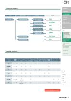
COUPLINGS ETP BUSHINGS ELECTROMAGNETIC CLUTCHES & BRAKES Clutches & Brakes SPEED CHANGERS & REDUCERS Butt shaft construction, drip-proof type LINEAR SHAFT DRIVES Motor-coupled type Clutch and brake units Through-shaft construction, open-disc brake system type CLUTCH AND BRAKE UNITS TORQUE LIMITERS ROSTA Speed reducerintegrated type Motor/speed reducer integrated type Double clutch and brake units ELECTROMAGNETIC-ACTUATED CLUTCHES AND BRAKES Double-clutch units ELECTROMAGNETICACTUATED MICRO CLUTCHES & BRAKES ELECTROMAGNETICACTUATED CLUTCHES & BRAKES ELECTROMAGNETIC CLUTCH & BRAKE UNITS...
Open the catalog to page 2
ELECTROMAGNETIC-ACTUATED CLUTCHES AND BRAKES ELECTROMAGNETIC CLUTCHES & BRAKES Product Lineup ■ Butt shaft construction, drip-proof type This design preserves the performance of Handling is made simpler by drip-proof construction clutch and brake to the maximum extent. that encloses clutch and brake inside a light alloy housing. ■ Mounting direction freedom Disc springs are used, so this clutch/brake unit can be used vertically. Its construction is sturdy, yet lightmass. Its easy-to-use butt-connected construction is drip proof, making it suitable for a variety of general industrial...
Open the catalog to page 3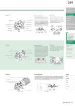
289 COUPLINGS ETP BUSHINGS ELECTROMAGNETIC Output shaft Bearing cover Bearing cover Brake stator Input shaft CLUTCHES & BRAKES ■ Power transmission Input and output shafts are isolated. A pulley or the like is mounted on the input shaft, connecting it to the driver so it is always rotating. When electricity flows to the clutch, the two shafts are connected, and rotation is transmitted. If the brake mounted on the output shaft is supplied with electricity simultaneous with clutch current being shut off, the input and output shafts are isolated and the output shaft is quickly braked. The end...
Open the catalog to page 4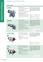
ELECTROMAGNETIC-ACTUATED CLUTCHES AND BRAKES ELECTROMAGNETIC CLUTCHES & BRAKES Product Lineup ■ Compact, space saving These are practical units in which worm These are very compact units that combine a worm reducers are directly connected to clutch/brake reducer and clutch/brake in a single unit. They can greatly save on space required for mounting. ■ Easy to mount and handle V pulley comes mounted as standard on the input A part, so simply connect it to a drive with a belt. Install the speed reducer to complete the mounting. No units in advance. A standard V belt pulley is installed on the...
Open the catalog to page 5
■ Power transmission V pulley is installed on the input part of the clutch, connected by a belt to the drive, A Worm gear speed reducer Clutch stator and rotates continuously. When current flows to the clutch, rotation is transmitted to the worm shaft, and the output shaft of the speed reducer rotates. If the brake is supplied with electricity when clutch current is shut off, the output shaft stops. Input (Belt transmission) SPEED CHANGERS Brake stator LINEAR SHAFT DRIVES Output (Speed reducer shaft) Speed reducer output shaft Worm gear speed reducer shaft CLUTCHES & BRAKES & REDUCERS Rotor...
Open the catalog to page 6
ELECTROMAGNETIC-ACTUATED CLUTCHES AND BRAKES ELECTROMAGNETIC CLUTCHES & BRAKES Customization Examples of Special Cases ■ Special friction material (lining) specifications In addition to standard friction materials, high-torque friction materials Input and output components that meet your needs, for example, by and long-life friction materials can also be handled. When using non- having V pulleys (including with different pulley diameters), sprockets, standard friction materials, the friction torque and total work will differ or timing pulleys, can be designed and produced. from catalog...
Open the catalog to page 7
293 ■ Integrated drive unit that connects a motor and special type of CBW model (hollow-shaft worm reducer) with a belt COUPLINGS ETP BUSHINGS ELECTROMAGNETIC CLUTCHES & BRAKES SPEED CHANGERS & REDUCERS INVERTERS LINEAR SHAFT DRIVES TORQUE LIMITERS ROSTA SERIES ELECTROMAGNETIC-ACTUATED CLUTCHES AND BRAKES ■ Integrated drive unit, covered with a safety cover, that connects a motor and a special CBW model worm reducer with a belt ELECTROMAGNETICACTUATED MICRO CLUTCHES & BRAKES ELECTROMAGNETICACTUATED CLUTCHES & BRAKES ELECTROMAGNETIC CLUTCH & BRAKE UNITS SPRING-ACTUATED BRAKE ELECTROMAGNETIC...
Open the catalog to page 8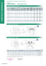
ELECTROMAGNETIC-ACTUATED CLUTCHES AND BRAKES Specifications (125- □ -12G) Torque decaying time td [s] Heat resistance class Torque build-up time tp [s] Armature pull-in time ta [s] Total work performed until readjustment of the air gap ET [J] Rotating part moment of inertia J [kg·m2] ELECTROMAGNETIC CLUTCHES & BRAKES 125 Models Clutch/Brake Units Max. rotation speed [min-1] Dynamic Static friction friction torque torque Td Ts [N·m] [N·m] * The dynamic friction torque, Td, is measured at a relative speed of 100 min-1. Depending on the initial torque characteristics, break-in to condition the...
Open the catalog to page 9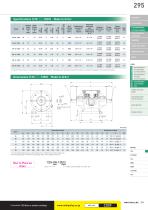
Heat resistance class Armature pull-in time ta [s] Total work performed until readjustment of the air gap ET [J] Rotating part moment of inertia J [kg·m2] Dynamic Static friction friction torque torque Td Ts [N·m] [N·m] Torque rise time tp [s] Torque extinction time td [s] LINEAR SHAFT DRIVES TORQUE LIMITERS ROSTA SERIES ELECTROMAGNETIC-ACTUATED CLUTCHES AND BRAKES & REDUCERS INVERTERS CLUTCHES & BRAKES SPEED CHANGERS * The dynamic friction torque, Td, is measured at a relative speed of 100 min-1. Depending on the initial torque characteristics, break-in to condition the engaging surfaces...
Open the catalog to page 10All Miki Pulley Europe AG catalogs and technical brochures
-
 STK Catalog
2 Pages
-
 BXR-LE Model datasheet
2 Pages
-
 Servoflex SFR series
4 Pages
-
 TT(03) Model datasheet
3 Pages
-
 BXL-N datasheet
1 Pages
-
 ASK Model datasheet
1 Pages
-
 ASK Model
2 Pages
-
 BXW Model datasheets
4 Pages
-
 TT Torque Tender
10 Pages
-
 SFM Model
8 Pages
-
 SFS Model
14 Pages
-
 SFC Model
12 Pages
-
 PSL - G Model
2 Pages
-
 Sprflex / Jaw Type
3 Pages
-
 Paraflex Pin Bush
4 Pages
-
 Posi Lock / Klemmelemente
18 Pages
-
 Spring-Actuated Brakes
34 Pages
-
 Power Supplies Brakes
26 Pages
-
 Electromagnetic clutch and brake
14 Pages
-
 SFF Model
14 Pages
-
 SFH Model
8 Pages
-
 DC Motors
12 Pages
-
 Speed change Pulley
20 Pages
-
 Baumannflex Models
8 Pages
-
 Starflex ALS Model
16 Pages
-
 KSK Model
2 Pages
-
 BXR-LE Model
2 Pages
-
 BXR Model
4 Pages
-
 BXW Model
4 Pages
-
 BXH Model
4 Pages
-
 BXL Model
4 Pages
-
 BXL-N Model
2 Pages
-
 SFF Model datasheets
9 Pages
-
 SFH Model datasheets
6 Pages
-
 SFM Model datasheets
4 Pages
-
 SFS Model datasheets
21 Pages
-
 Paraflex CPE, CPU
2 Pages
-
 CHP Model datasheet
1 Pages
-
 BXR Model datasheet
2 Pages
-
 BXH Model datasheet
2 Pages
-
 BXL Model datasheet
2 Pages
-
 102, 112, CYT datasheets
8 Pages
-
 121, 122, 125 datasheets
3 Pages
-
 SFC Model Datasheet
6 Pages
-
 TT(01) Model datasheet
3 Pages
-
 KSK Model datasheet
1 Pages
-
 STK Model datasheet
1 Pages
-
 DMB Model datasheet
1 Pages
-
 SRG Model datasheet
1 Pages


