- Catalogs
- microsonic
- ucs ultrasonic sensors
- Company
- Products
- Catalogs
- News & Trends
- Exhibitions
ucs ultrasonic sensors
1 /13Pages

ucs ultrasonic sensors
1 /13Pages
Catalog excerpts
Extract from our online catalogue: ucs ultrasonic sensors Current to: 2025-01-27 microsonic GmbH / Phoenixseestraße 7 / 44263 Dortmund / Germany / T +49 231 975151-0 / F +49 231 975151-51 / E [email protected] microsonic® is a registered trademark of microsonic GmbH. All rights reserved.
Open the catalog to page 1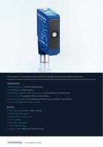
The ucs sensors in a sturdy metal housing are mechanically compatible with the industrial standard of opto sensors. HIGHLIGHTS > Robust metal housing > for harsh usage conditions > Dovetail design > for fast installation > Mechanically compatible with the industry standard > a true alternative to the optical sensor > IO-Link interface > for support of the new industry standard > Automatic synchronisation > for simultaneous operation of up to ten sensors in close quarters > UL Listed to Canadian and US safety standards > 2 Push-Pull switching outputs > pnp or npn basis > Antivalent switching output...
Open the catalog to page 2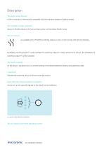
Description The sturdy metal housing of the ucs sensors is mechanically compatible with the industrial standard of optical sensors. The rotatable circular connector allows for flexible selection of the mounting location and facilitates flexible wiring. The ucs sensors are available with 2 Push-Pull switching outputs in pnp- or npn-circuitry with IO-Link interface. By default, switching output F1 works antivalent to switching output F2. Using LinkControl or IO-Link, the antivalence of switching output F1 can be canceled. The Teach-in button on the sensor´s top allows for a convenient setting of...
Open the catalog to page 3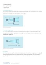
Single switching point Two-way reflective barrier Window mode The switched output is set by positioning the object to be detected within the desired distance (1) to the sensor, pressing the button for approx. 3 seconds and then pressing it once more for approx. 1 second. Ready. Teach-in of a switching point A two-way reflective barrier can be set up with the help of a permanently mounted reflector by mounting the ucs sensor and the reflector, then pressing the button for approx. 3 seconds and then pressing it once more for approx. 10 seconds. Now, the two-way reflective barrier has been set. Teach-in...
Open the catalog to page 4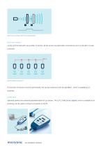
Teach-in of a window with two switching points Up to ten sensors can be synchronised with one another. To do this, all the sensors are electrically connected on pin 5 on the M12 circular connector. If more than 10 sensors must be synchronised, this can be carried out with the SyncBox1 , which is available as an accessory. LinkControl optionally permits the extensive parameterisation of ucs sensors. The LCA-2 LinkControl adapter, which is available as an accessory, can be used to connect ucs sensors to the PC.
Open the catalog to page 5
Sensor connected to the PC via LCA-2 for programming IO-Link integrated in version 1.1.2 The ucs ultrasonic sensors are equipped with Smart Sensor Profile, which creates more transparency between IO-Link devices.
Open the catalog to page 6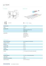
scale drawing 2 x Push-Pull measuring range design operating mode ultrasonic-specific means of measurement transducer frequency blind zone operating range maximum range resolution reproducibility accuracy proximity switch/reflective mode reflective barrier window mode cuboidal design narrow sound field IO-Link version 1.1 Smart Sensor Profile UL Listed echo propagation time measurement ± 1 % (temperature drift internally compensated) operating voltage UB 10 - 30 V d.c., reverse polarity protection type of connection 5-pin M12 initiator plug
Open the catalog to page 7
micro/onic ucs ultrasonic sensors
Open the catalog to page 8
switching output Push-Pull, UB-3 V, -UB+3 V,Imax = 100 mA NOC/NCC adjustable, short-circuit-proof switching output Push-Pull, UB-3 V, -UB+3 V,Imax = 100 mA NOC/NCC adjustable, short-circuit-proof switching hysteresis switching frequency response time delay prior to availability com input synchronisation input teach-in input IO-Link product name format of process data content of process data Bit 0: Q1 switch status; Bit 1-15: distance value with a resolution of 0,1 mm ISDU paramter Identification, measuring configuration, switched output, filter, temperature compensation, operation system commands...
Open the catalog to page 9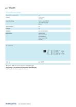
ucs-15/CFF technical features/characteristics temperature compensation Teach-in via push-button LCA-2 with LinkControl IO-Link Duo-LED green/yellow cuboidal design narrow sound field IO-Link version 1.1 Smart Sensor Profile UL Listed The content of this document is subject to technical changes. Specifications in this document are presented in a descriptive way only. They do not warrant any product features.
Open the catalog to page 10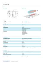
scale drawing 2 x Push-Pull measuring range design operating mode ultrasonic-specific means of measurement transducer frequency blind zone operating range maximum range resolution reproducibility accuracy proximity switch/reflective mode reflective barrier window mode cuboidal design IO-Link version 1.1 Smart Sensor Profile UL Listed echo propagation time measurement ± 1 % (temperature drift internally compensated) operating voltage UB 10 - 30 V d.c., reverse polarity protection type of connection 5-pin M12 initiator plug
Open the catalog to page 11
switching output Push-Pull, UB-3 V, -UB+3 V,Imax = 100 mA NOC/NCC adjustable, short-circuit-proof switching output Push-Pull, UB-3 V, -UB+3 V,Imax = 100 mA NOC/NCC adjustable, short-circuit-proof switching hysteresis switching frequency response time delay prior to availability com input synchronisation input teach-in input IO-Link product name format of process data content of process data Bit 0: Q1 switch status; Bit 1-15: distance value with a resolution of 0,1 mm ISDU paramter Identification, measuring configuration, switched output, filter, temperature compensation, operation system commands...
Open the catalog to page 12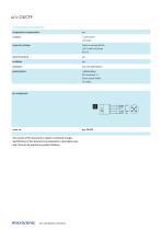
ucs-24/CFF technical features/characteristics temperature compensation Teach-in via push-button LCA-2 with LinkControl IO-Link Duo-LED green/yellow cuboidal design IO-Link version 1.1 Smart Sensor Profile UL Listed The content of this document is subject to technical changes. Specifications in this document are presented in a descriptive way only. They do not warrant any product features.
Open the catalog to page 13All Microsonic catalogs and technical brochures
 pico+ ultrasonic sensors
78 Pages
 Online Catalogue ultrasonic sensors
172 Pages
 cube ultrasonic sensors
33 Pages
 zws ultrasonic sensors
81 Pages
 wms ultrasonic distance sensors
20 Pages
 sks ultrasonic proximity switch
21 Pages
 crm+ ultrasonic level sensors
75 Pages
 pico+TF ultrasonic level sensors
41 Pages
 nero ultrasonic proximity switch
100 Pages
 bks+ ultrasonic edge sensors
10 Pages
 nano M12 ultrasonic sensor
19 Pages
 lcs+ ultrasonic sensors
24 Pages
 bks ultrasonic edge sensors
13 Pages
 mic ultrasonic sensors
46 Pages
 lpc+ ultrasonic sensors
77 Pages
 lcs ultrasonic sensors
33 Pages
 LCA-2
LCA-211 Pages
 hps+ ultrasonic level sensors
44 Pages
 esp-4 label/splice sensor
23 Pages
 hps+25/DIU/TC/E/G1
44 Pages
 crm+25/D/TC/E
75 Pages
 mic+ ultrasonic sensors
191 Pages


- Microsonic proximity sensor
- Level probe
- Liquid level sensor
- Cylindrical proximity sensor
- Analog level sensor
- Microsonic IP67 proximity sensor
- Industrial detector
- Digital output level sensor
- Vessel level sensor
- DC proximity sensor
- Microsonic distance sensor
- Stainless steel level sensor
- Plastic proximity sensor
- Threaded proximity sensor
- Rectangular proximity sensor
- Water level sensor
- IP67 level sensor
- PNP proximity sensor
- Analog detector
- M12 proximity sensor