- Catalogs
- microsonic
- mic+ ultrasonic sensors
- Company
- Products
- Catalogs
- News & Trends
- Exhibitions
mic+ ultrasonic sensors
1 /191Pages

mic+ ultrasonic sensors
1 /191Pages
Catalog excerpts

Extract from our online catalogue: mic+ ultrasonic sensors Current to: 2025-01-27 microsonic GmbH / Phoenixseestraße 7 / 44263 Dortmund / Germany / T +49 231 975151-0 / F +49 231 975151-51 / E [email protected] microsonic® is a registered trademark of microsonic GmbH. All rights reserved.
Open the catalog to page 1
mic+ sensors are available in four device designs with five different detection ranges > Digital display with direct measured value output in mm/cm or % > IO-Link interface > for support of the new industry standard > Numeric configuration of the sensor using digital display > permits complete advance configuration of the sensor > Automatic synchronisation and multiplex operation > for simultaneous operation of up to ten Sensors in close quarters > UL Listed to Canadian and US safety standards > 1 Push-Pull switching output > pnp or npn basis > 1 or 2 switching outputs > in pnp or npn variants...
Open the catalog to page 2
Description The mic+ sensor family embedded in its M30 housing design covers a measuring range from 30 mm to 8 m with its five detection ranges. Depending on the detection range, the internal resolution for distance measurement is 0.025 or 2.4 mm. All sensors are equipped with integrated temperature compensation. TouchControl with LED Display Four different output levels are available for all five detection ranges: 1 switching output, optionally in pnp, npn or Push-Pull circuitry 2 switching outputs, optionally in pnp or npn circuitry 1 analogue output with an additional pnp switching output With...
Open the catalog to page 3
via the LED display without the object to be detected being positioned within the detection range. Therefore, it is possible to completely set the sensor without the help of auxiliary reflectors, even outside the actual application. Two three-colour LEDs always indicate the current status of the switching outputs and/or the analogue output. Further additional function (add-ons) are available as an option within the TouchControl menu structure. Measured distances can be smoothed with different measurement filters, e.g., be stressed by means of the ten level software filter, from F00 (direct measuring...
Open the catalog to page 4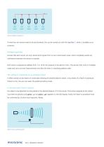
If more than ten sensors need to be synchronised, this can be carried out with the SyncBox1 , which is available as an accessory. Multiplex operation ensures that each sensor can only receive echo signals from its own transmission pulse, which completely avoids any interference between the sensors (crosstalk). Each sensor is assigned an address from 1 to 10 for this purpose in the add-on menu. The sensors then work in multiplex mode and carry out their measurements one after the other in ascending address order. The setting of a switching or an analogue output is either carried out by means of...
Open the catalog to page 5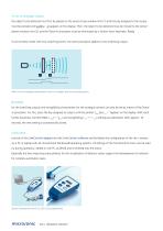
To set an analogue output the object to be detected must first be placed on the sensor-close window limit (1) and the key assigned to the output appears on the display. Then, the object to be detected must be moved to the sensor- must be pressed until distant window limit (2) and the Teach-in procedure must be terminated by a further short keystroke. Ready. To set window mode with two switching points, the same procedure applies to one switching output. Teach-in of an analogue characteristic curve or a window with two switching points NCC/NOC for the switching outputs and rising/falling characteristic...
Open the catalog to page 6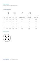
lO-Link integrated in version 1.1 for sensors with switching output. Pin assignment Pin PNP NPN PNP NPN Analogue output 1 PNP output + Analogue 1 +Ub +Ub +Ub +Ub Colour code of sensor cable brown micro/onic mic+ ultrasonic sensors
Open the catalog to page 7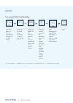
Numerical setting via LED display Press both keys until "Pro" for programming is shown on the LED display. Select the output to be set (according to sensor type d1, d2 or IU). switching point (or, with analogue outputs, the sensor-close window limit) in mm/cm. If window mode is required for the switching output, the rear window limit must be set (or, with between NCC and NOC (or with analogue outputs, between rising and falling characteristics). For numerical input, the object to be detected needs not to be placed within the sensor's detection range. micro/onic mic+ ultrasonic sensors
Open the catalog to page 8
You have special requirements? Nothing as simple as that. With us, you can easily find an individual solution. Let us talk about your application: +49 231 97 51 51-82. TECHNICAL SUPPORT TEAM mic+ ultrasonic sensor
Open the catalog to page 9
scale drawing detection zone 1 x Push-Pull measuring range design operating mode ultrasonic-specific means of measurement transducer frequency blind zone operating range maximum range resolution reproducibility accuracy proximity switch/reflective mode reflective barrier window mode IO-Link Version 1.1 Smart Sensor Profile UL Listed echo propagation time measurement ± 1 % (temperature drift internally compensated) operating voltage UB 9 - 30 V d.c., reverse polarity protection type of connection 5-pin M12 initiator plug
Open the catalog to page 10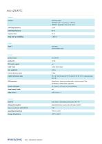
output 1 switching output Push-Pull, Ub-3 V, -Ub+3 V,Imax = 100 mA NOC/NCC adjustable, short-circuit-proof synchronisation input IO-Link product name product ID SIO mode support COM mode min. cycle time format of process data content of process data ISDU paramter system commands Smart Sensor Profile IODD version Bit 0: Q1 switch status; Bit 8-15: scale (Int. 8); Bit 16-31: measured value (Int. 16) Identification, measuring configuration, switched output, filter, temperature compensation, operation SP1 Teach-in, SP2 Teach-in, factory settings material brass sleeve, nickel-plated, plastic parts,...
Open the catalog to page 11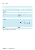
mic+25/F/TC technical features/characteristics temperature compensation 2 push-buttons + LED display (TouchControl) Teach-in and numeric configuration via TouchControl LCA-2 with LinkControl IO-Link Display IO-Link Version 1.1 Smart Sensor Profile UL Listed The content of this document is subject to technical changes. Specifications in this document are presented in a descriptive way only. They do not warrant any product features. mic+ ultrasonic sensors
Open the catalog to page 12All Microsonic catalogs and technical brochures
 pico+ ultrasonic sensors
78 Pages
 Online Catalogue ultrasonic sensors
172 Pages
 cube ultrasonic sensors
33 Pages
 zws ultrasonic sensors
81 Pages
 wms ultrasonic distance sensors
20 Pages
 ucs ultrasonic sensors
13 Pages
 sks ultrasonic proximity switch
21 Pages
 crm+ ultrasonic level sensors
75 Pages
 pico+TF ultrasonic level sensors
41 Pages
 nero ultrasonic proximity switch
100 Pages
 bks+ ultrasonic edge sensors
10 Pages
 nano M12 ultrasonic sensor
19 Pages
 lcs+ ultrasonic sensors
24 Pages
 bks ultrasonic edge sensors
13 Pages
 mic ultrasonic sensors
46 Pages
 lpc+ ultrasonic sensors
77 Pages
 lcs ultrasonic sensors
33 Pages
 LCA-2
LCA-211 Pages
 hps+ ultrasonic level sensors
44 Pages
 esp-4 label/splice sensor
23 Pages
 hps+25/DIU/TC/E/G1
44 Pages
 crm+25/D/TC/E
75 Pages


- Microsonic proximity sensor
- Level probe
- Liquid level sensor
- Cylindrical proximity sensor
- Analog level sensor
- Microsonic IP67 proximity sensor
- Industrial detector
- Digital output level sensor
- Vessel level sensor
- DC proximity sensor
- Microsonic distance sensor
- Stainless steel level sensor
- Plastic proximity sensor
- Threaded proximity sensor
- Rectangular proximity sensor
- Water level sensor
- IP67 level sensor
- PNP proximity sensor
- Analog detector
- M12 proximity sensor