
Catalog excerpts
Simulink Design Verifier Identify design errors, generate test cases, and verify designs against requirements Simulink Design Verifier™ uses formal methods to identify hard–to-find design errors in models without requiring extensive tests or simulation runs. Design errors detected include dead logic, integer overflow, division by zero, and violations of design properties and assertions. Simulink Design Verifier highlights blocks in the model containing these errors and blocks proven to be without them. For each block with an error, it calculates signal-range boundaries and generates a test vector that reproduces the error in simulation. The generated test vectors provide simulation inputs that exercise functionality captured in the model structure and specified by the test objectives. The test vectors, together with the design properties and test objectives, can be used to verify code running in software-in-the-loop (SIL) and processor-in-the-loop (PIL) test configurations. Learn more about verification, validation, and test in Model-Based Design and support for certification standards in automotive, aerospace, and industrial automation applications. Key Features ▪ Polyspace® and Prover Plug-In® formal analysis engines ▪ Detection of dead logic, integer and fixed-point overflows, division by zero, and violations of design properties ▪ Blocks and functions for modeling functional and safety requirements ▪ Test vector generation from functional requirements and model coverage objectives, including condition, decision, and modified condition/decision (MCDC) ▪ Property proving, with generation of violation examples for analysis and debugging ▪ Fixed-point and floating-point model support Simulink Design Verifier enables you to perform model analysis within the Simulink® environment. It lets you verify your designs and validate requirements early without having to generate code. As a result, you can perform verification and validation throughout the design process. Model analysis with Simulink Design Verifier complements simulation by letting you use simulation results as inputs to analysis with formal methods. Simulink Design Verifier supports the discrete-time subset of Simulink and Stateflow® typically used in embedded control designs.
Open the catalog to page 1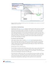
Design Verifier Rtiults Back to summary - Close result5 it* Q\ip\ay Diagram Simulation £natyiii £ede JMIS JJetp s Id vdem o_cru ise_conti ol_fxp_f ixed / Fixed - Point Controller/Sumi Overflow ERROR- View test case Derived Ranges: mo.ciuise.control.fsp.fKed: ► Fixed-Pc int Controller ► target speed JtJHi En:- ~ir;:i;t speed ^^sfirl6_Erta error throt Design error detection in a model using Simulink Design Verifier. The block highlighted in red has a design error; the subsystem highlighted in green is proven correct. Formal Methods in Model-Based Design Simulink Design Verifier uses formal...
Open the catalog to page 2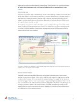
Red blocks have design errors. For red blocks, Simulink Design Verifier generates a test case that can reproduce the problem during simulation or testing. You can invoke the test case and run a simulation directly within Detecting Dead Logic You use the test-generation mode in Simulink Design Verifier to detect dead logic, which represents model objects that are either obsolete or are proven to stay inactive during execution. Often dead logic is caused by a design or a requirement error. During code generation, dead logic leads to dead code. Dead logic is difficult to detect by testing in...
Open the catalog to page 3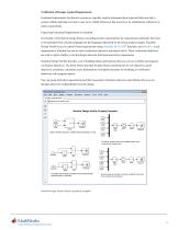
Verification of Designs Against Requirements Functional requirements for discrete systems are typically explicit statements about expected behaviors that a system exhibits and behaviors that it must never exhibit. Behaviors that must never be exhibited are referred to as safety requirements. Expressing Functional Requirements in Simulink To formally verify that the design behaves according to these requirements, the requirements statements first need to be translated from a human language into the language understood by the formal analysis engine. Simulink Design Verifier lets you express...
Open the catalog to page 4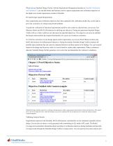
When you use Simulink Design Verifier with the Requirements Management Interface in Simulink Verification and Validation™, you can link blocks and functions used to capture requirements and verification objectives to the higher-level textual requirements outside of Simulink. Proving Designs Against Requirements Once requirements and verification objectives have been captured in the verification model, they can be used to prove the correctness of a design using formal methods. To guide the verification of functional requirements and drive your system to a desired state, you can use Test...
Open the catalog to page 5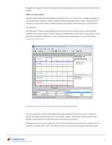
debugging by using proof objectives that represent safety requirements to stop simulation at the moment of their Model Coverage Analysis Simulink Design Verifier analyzes algorithms and logic in your Simulink and Stateflow models to generate test cases and parameters required by industry standards for developing high-integrity systems. Test generation for structural coverage criteria includes condition, decision, and modified condition/decision coverage (MC/DC). Test Generation Test generation for model coverage augments requirements-based tests created by hand or collected during...
Open the catalog to page 6
Validation of Generated Test Vectors To validate generated test vectors that meet structural coverage criteria, you can use the Model Coverage tool provided in Simulink Verification and Validation. It monitors simulation and measures whether the objectives reported during formal analysis have been achieved. In addition to coverage objectives for condition, decision, and MC/DC coverage, the Model Coverage tool also reports on the coverage of test objectives, proof objectives, assumptions, constraints, lookup tables, and signal ranges recorded during simulation. Simulink Design Verifier is...
Open the catalog to page 7All The MathWorks catalogs and technical brochures
-
 MATLAB Production Server
6 Pages
-
 Database Toolbox
4 Pages
-
 MATLAB Report Generator
4 Pages
-
 Stateflow
8 Pages
-
 SimEvents
7 Pages
-
 SimDriveline
7 Pages
-
 SimHydraulics
7 Pages
-
 SimPowerSystems
8 Pages
-
 Simulink Control Design
5 Pages
-
 Aerospace Blockset
5 Pages
-
 SimRF
SimRF6 Pages
-
 Simulink Coder
6 Pages
-
 Embedded Coder
8 Pages
-
 Simulink PLC Coder
4 Pages
-
 Fixed-Point Designer
9 Pages
-
 MATLAB Coder
5 Pages
-
 Simulink 3D Animation
10 Pages
-
 Gauges Blockset
2 Pages
-
 Simulink Report Generator
3 Pages
-
 Polyspace Bug Finder
6 Pages
-
 global-optimization-toolbox
10 Pages
-
 Phased Array System Toolbox
9 Pages
-
 OPC Toolbox
5 Pages
-
 Simulink Design Optimization
10 Pages
-
 Filter Design HDL Coder
5 Pages
-
 Bioinformatics Toolbox
9 Pages
-
 SimBiology
6 Pages
-
 Computer Vision System Toolbox
10 Pages
-
 DSP System Toolbox
11 Pages
-
 Fuzzy Logic Toolbox
5 Pages
-
 Polyspace Client for C/C++
5 Pages
-
 xPC Target
5 Pages
-
 SimMechanics
7 Pages
-
 Simscape
7 Pages
-
 Simulink
6 Pages
-
 Data Acquisition Toolbox
8 Pages
-
 Image Processing Toolbox
7 Pages
-
 Signal Processing Toolbox
10 Pages
-
 Control System Toolbox
6 Pages
-
 Symbolic Math Toolbox?
6 Pages
-
 Parallel Computing Toolbox?
7 Pages
-
 MATLAB®
6 Pages
-
 Mapping Toolbox 3.2
7 Pages
-
 Instrument Control Toolbox
7 Pages
-
 Optimization Toolbox 6.0
14 Pages


Archived catalogs
-
 MATLAB Release Notes
505 Pages
-
 C and Fortran API Reference
263 Pages
-
 External Interfaces
649 Pages
-
 Function Reference: Volume 3 (P-Z)
1696 Pages
-
 Function Reference: Volume 2 (F-O)
1568 Pages
-
 Function Reference: Volume 1 (A-E)
1298 Pages
-
 Creating Graphical User Interfaces
520 Pages
-
 3-D Visualization
212 Pages
-
 Graphics
667 Pages
-
 MATLAB Programming Tips
66 Pages
-
 Programming Fundamentals
840 Pages
-
 Data Analysis
220 Pages
-
 Mathematics
316 Pages
-
 MATLAB® Getting Started Guide
250 Pages

