- Catalogs
- Marsh Bellofram
- Marsh Bellofram PCD Division Type 1500 I/P and E/P Transducers
Marsh Bellofram PCD Division Type 1500 I/P and E/P Transducers
1 /5Pages

Marsh Bellofram PCD Division Type 1500 I/P and E/P Transducers
1 /5Pages
Catalog excerpts

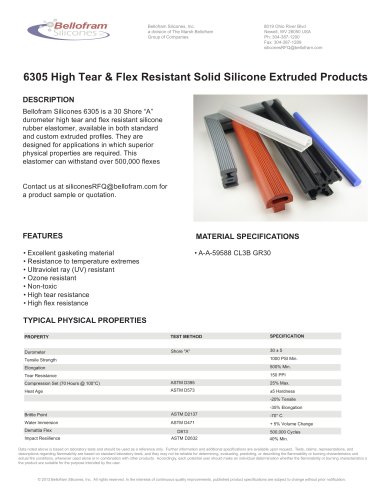
www.marshbellofram.com • 800.727.5646 67 Transducers Type 1500 Description The T-1500 is a new series of electro-pneumatic transducers that convert an electrical signal to a proportional pressure output. It provides precision electro-pneumatic control to actuators, valves, positioners, final control elements and is ideally used for high-flow control devices. The Type 1500's compact size and accessibility to ports and adjustments allow the unit to be installed in space-constrained locations or in a manifold for multi-device control. DIN rail and manifold assemblies are available in kits that provide three, five or ten mounting points. An integral pneumatic volume booster is included in the Type 1500 design to provide high flow capacity. (See specifications for flow data.) Standard Features • Small footprint, compact size • Manifold mounting configurations • Built-in volume booster • Electrical Connections: Conduit 12 NPT or BSPT, Terminal Block, Hirschmann® Connectors (DIN 43 650-A) • Supply and output ports on front and back of unit • Low air consumption • External zero and span adjustments • Low cost • Field accessible orifice • Electrical conduit connection meets CE requirements Options Available • Intrinsically Safe (FM, CSA, ATEX) • NEMA 4X (FM, CSA) Excludes Terminal Block Applications The T-1500 transducer can be used as an electro-pneumatic control device to operate: • Valve actuators • Valve positioners • HVAC systems • Material handling systems • Paper handling controls • Automation systems • Liquid and gas processing systems Type 1500 I/P & E/P Transducers Principle of Operation (See Fig. 2 and 6) The T-1500 Transducer is a force balance device in which a coil is suspended in the field of a magnet by a flexure. Current flowing through the coil generates axial movement of the coil and flexure. The flexure moves against the end of a nozzle and creates a back pressure in the nozzle by restricting air flow. This back pressure acts as a pilot pressure to an integral booster relay. Consequently, as the input signal increases (or decreases for reverse acting), output pressure increases proportionally. In the zero based T-1500, the output of the transducer section is routed to an integral negative bias booster relay. The bias relay allows the complete unit to regulate output pressure down to 0 psig/BAR. The bias relay also amplifies the output of the transducer which allows the zero based units to regulate higher output pressures than the standard T-1500. Zero and Span are calibrated by turning easily accessible adjusting screws on the front face of the unit (see Figures 3, 4, 5, 7, 8 and 9). The zero adjustment causes the nozzle to move relative to the flexure. The span adjustment is a potentiometer that limits the flow of current through the coil. A thermistor circuit in series with the coil provides temperature compensation. Mounting The T-1500 can be mounted at any angle but should be calibrated after mounting. For maximum output pressure stability, the T-1500 should be mounted vertically in a vibration free location or such that the vibration is isolated to the X and Z axis. The T-1500 can be in-line, panel, pipe, DIN rail or manifold mounted. Air Connections 1. Supply Air must be instrument quality air regulated between 5 PSI above maximum output pressure up to 120 PSIG / 8.3 BAR (See table: Supply Pressure Range). 2. Instrument-quality air consists of: a. A dew point less than 35¢ªF b. No particles larger than three microns c. Maximum oil content of 1 ppm 3. All unused ports must be plugged. Type 1500 Transducers Supply Connect supply to either of two ports marked “IN” on the base of the transducer. Avoid getting pipe sealant inside the piping or transducer. Output Connect output to either of two ports marked “OUT” on the base of the transducer. The second “OUT” port may be used for a pressure gauge.
Open the catalog to page 1
68 800.727.5646 • www.marshbellofram.com Transducers Type 1500 Transducers Standard Range Zero Based Hysteresis <0.75% of span <1.0% of span Repeatability <0.5% of span <0.5% of span Linearity (Independent) <0.75% of span <1.0% of span for fluorocarbon units <1.0% of span Flow @ Mid Range 6.5 SCFM (Minimum) @ 15.0 PSIG / 1.0 BAR output pressure, 120 PSIG / 8.3 BAR supply pressure 9.0 SCFM (Minimum) @ 15.0 PSIG / 1.0 Bar output pressure, 150 PSIG / 10.3 BAR supply pressure Maximum Air Consumption 3 SCFH @ 15 PSI / 1.0 BAR output pressure 18 SCFH @ Maximum output pressure Exhaust Capacity >1.0...
Open the catalog to page 2
www.marshbellofram.com • 800.727.5646 69 Transducers T-1500 Manifold and Adapter Kit Principle of Operation The T-1500 manifold assembly allows multiple T-1500 Transducers to be mounted in parallel. This minimizes the number of individual supply air lines required. Manifolds are available to hold three, five, or ten units. Each manifold comes with check valves so that a unit can be pulled off of the manifold for service or replacement without affecting the whole manifold. (See Figure 1.) Mounting The manifolds may be mounted flush with a wall or cabinet or may be mounted away from the wall. Both...
Open the catalog to page 3
70 800.727.5646 • www.marshbellofram.com Transducers Type 1500 Extended Range Parts Number Description 1 Circuit Board 2 Worm Gear 3 Duckbill Valve (NEMA 4X Only) 4 Magnet Assembly 5 Nozzle Assembly 6 Bonnet Gasket (NEMA 4X Only) 7 Servo Diaphragm (I/P Section) 8 Control Diaphragm (I/P Section) 9 Pintle 10 Supply Seat 11 Coil/Flexure Assembly 12 Servo Diaphragm (Bias Relay) 13 Control Diaphragm (Bias Relay) 14 Orifice Screw 15 Bias Spring Figure 2: Type 1500 Extended Range Parts Figure 3: Terminal Block IN IN OUT OUT Z SPAN ADJUSTMENT ORIFICE SCREW ZERO ADJUSTMENT S 2.87" 62.9mm 5.27" 133.9mm...
Open the catalog to page 4
www.marshbellofram.com • 800.727.5646 71 Transducers Type 1500 Standard Range Parts Number Description 1 Circuit Board 2 Worm Gear 3 Duckbill Valve (NEMA 4X Only) 4 Magnet Assembly 5 Nozzle Assembly 6 Bonnet Gasket (NEMA 4X Only) 7 Servo Diaphragm (I/P Section) 8 Control Diaphragm (I/P Section) 9 Pintle 10 Supply Seat 11 Coil/Flexure Assembly Figure 6: Type 1500 Standard Range Parts Back Dimensions Figure 7: Terminal Block Figure 9: Hirschmann® (DIN 43 650-A) Type 1500 Standard Range Dimensions FIGURE 8: 1/2 NPT / BSPT OUT IN 1.52" 38.6mm 1.00" 25.4mm 10-32 UNF-2B MOUNTING HOLES 0.77" 19.6mm...
Open the catalog to page 5All Marsh Bellofram catalogs and technical brochures
 Full Catalog BelGAS
307 Pages
 5204
52041 Page
 P627 High Flow Gas Regulator
10 Pages
 P212 Pressure Regulator
16 Pages
 P200 Pressure Regulator
19 Pages
 P95H Regulator
15 Pages
 P99 Pressure Reducing Regulator
11 Pages
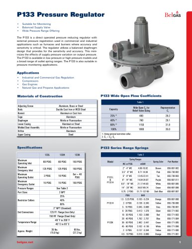 P133 Pressure Regulator
12 Pages
 P140 Pressure Regulator
4 Pages
 P303 Pressure Regulator
11 Pages
 P300 Pressure Regulator
11 Pages
 P203 Pressure Reducing Regulator
18 Pages
 F300 Pressure Regulator
7 Pages
 P600 Pressure Regulator
7 Pages
 P289RC Exhaust Booster
2 Pages
 W627 Liquid Gas Regulator
8 Pages
 F627 High Flow Gas Regulator
7 Pages
 BELLOFOAM™ 7804
1 Page
 BELLOFOAM™ 7704
1 Page
 BELLOFOAM™ 7604
1 Page
 Marsh Catalog
84 Pages
 P79 Air Relays
4 Pages
 Automated Timing & Controls
142 Pages
 Motor Protection
86 Pages
 Digital Controllers
30 Pages
 P630 High Flow Gas Regulator
12 Pages
 P39 Standard Gas Regulators
4 Pages
 P40 & P40 NACE Regulators
2 Pages
 P912 Pressure Regulator
2 Pages
 P119 Control Valve
4 Pages
 BelGAS Product Overview LT5040
12 Pages
 KING-GAGE Product Catalog
12 Pages
 BelGas P200 Pressure Regulator
18 Pages