- Catalogs
- Marsh Bellofram
- Marsh Bellofram BelGAS Division P912 Pressure Regulator
Marsh Bellofram BelGAS Division P912 Pressure Regulator
1 /2Pages

Marsh Bellofram BelGAS Division P912 Pressure Regulator
1 /2Pages
Catalog excerpts

P912 PART MATRIX P912 1 0 0 0 0 0 OUTLET PORT SIZE 14" 02 38" 03 OUTPUT PRESSURE 3"-7" W.C. 020 5"-10" W.C. 040 9.25" -13" W.C. 060 10" W.C.-1.05 psig 080 0.5-2.7 psig 100 2.7-5 psig 120 VENT CONNECTION: 1/8" NPT WITH REMOVABLE SCREEN 79.3 3.12 3.3 0.13 68.8 2.71 12.7 0.5 50.3 1.98 92.0 3.62 12.7 0.5 ITEM DESCRIPTION PART NUMBER 1 Body, 14"X 38" Port Zinc Body, 14"X 14" Port, Zinc 664-310-000 664-311-000 2 Arm assembly, nitrile/zinc 827-009-000 3 Rod, Stainless Steel 646-540-000 4 Machine Screw 516", plated steel (qty. 2) 648-000-417 5 Machine Screw 38", plated steel (qty. 6) 648-000-418 6 Backup...
Open the catalog to page 2All Marsh Bellofram catalogs and technical brochures
 Full Catalog BelGAS
307 Pages
 5204
52041 Page
 P627 High Flow Gas Regulator
10 Pages
 P212 Pressure Regulator
16 Pages
 P200 Pressure Regulator
19 Pages
 P95H Regulator
15 Pages
 P99 Pressure Reducing Regulator
11 Pages
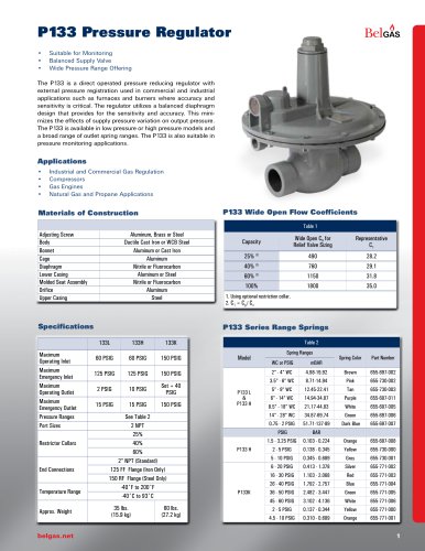 P133 Pressure Regulator
12 Pages
 P140 Pressure Regulator
4 Pages
 P303 Pressure Regulator
11 Pages
 P300 Pressure Regulator
11 Pages
 P203 Pressure Reducing Regulator
18 Pages
 F300 Pressure Regulator
7 Pages
 P600 Pressure Regulator
7 Pages
 P289RC Exhaust Booster
2 Pages
 W627 Liquid Gas Regulator
8 Pages
 F627 High Flow Gas Regulator
7 Pages
 BELLOFOAM™ 7804
1 Page
 BELLOFOAM™ 7704
1 Page
 BELLOFOAM™ 7604
1 Page
 Marsh Catalog
84 Pages
 P79 Air Relays
4 Pages
 Automated Timing & Controls
142 Pages
 Motor Protection
86 Pages
 Digital Controllers
30 Pages
 P630 High Flow Gas Regulator
12 Pages
 P39 Standard Gas Regulators
4 Pages
 P40 & P40 NACE Regulators
2 Pages
 P912 Pressure Regulator
2 Pages
 P119 Control Valve
4 Pages
 BelGAS Product Overview LT5040
12 Pages
 KING-GAGE Product Catalog
12 Pages
 BelGas P200 Pressure Regulator
18 Pages


Archived catalogs


- Valve
- Connector
- Manual valve
- Cylinder
- Temperature probe
- Electrical power supply connector
- On/off valve
- Angular encoder
- Incremental encoder
- Pressure gauge
- Pressure limiter
- Profile
- Double-acting cylinder
- Gas valve
- Level probe
- Single-stage pressure regulator
- Rectangular connector
- Liquid level sensor
- Pneumatic cylinder
- Incremental rotary encoder