- Catalogs
- Marsh Bellofram
- Marsh Bellofram Automatic Timing & Controls 405A Series Timer with Instantaneous Relay
Marsh Bellofram Automatic Timing & Controls 405A Series Timer with Instantaneous Relay
1 /3Pages

Marsh Bellofram Automatic Timing & Controls 405A Series Timer with Instantaneous Relay
1 /3Pages
Catalog excerpts

405A Series Automatic Timing & Controls automatictiming.com 800.727.5646 221/16 DIN Timers // 405A Series Instantaneous & Delayed: A version of the 405A is available with one set of SPDT instantaneous contacts and one set of SPDT delayed contacts. The instantaneous contacts transfer as soon as the timer is powered. The delayed contacts transfer at time out. This contact arrangement can be used to replace many conventional timers. On Delay/Interval Timing Mode Version: A version of the 405A is available with selectable ON-delay or Interval timing modes. This version has a set of DPDT output contacts. When in the ON-delay mode, the contacts transfer at time out. When in the Interval mode, the contacts transfer when power is applied and release at time out. Universal Power: All 405A timers can be powered using 24-240 VAC or 24 VDC power, greatly simplifying ordering and inventory management of replacement units. 1/16 DIN Housing: The 48mm2 (1/16 DIN) housing is compact and is watertight when panel mounted. The 405A is mounted in an 8-pin round (octal) socket. With an optional mounting clip, the 405A can be panel mounted. The Dial on the 405A is extra large and is easy to read. When fractional ranges are selected, decimal points are clearly indicated. The Mode select and Range select switches are located on the side of the unit, so that when panel mounted, these switches are not accessible to the operator. This tamper proof feature prevents unauthorized or hazardous changes to the timing mode and range from being made. Cycle Progress Indication: The 405A LED indicator provides a unique and effective method of cycle progress indication. Off before timing, the LED blinks at an ever increasing rate as the cycle progresses: once every 3-1/2 seconds during the first 10% of the cycle, twice during the second 10%, and so on. At time out, the LED pulses at a high rate. (In the 1, 5, 10 and 50 second ranges, the LED is OFF before timing, steady ON during timing, and pulsing ON after time-out). Timing begins when the start switch is closed. This starts an oscillator which runs at a frequency determined by the time setting. A fixed number of counts from the oscillator determines the end of the timing cycle. The time required to accomplish this depends upon the oscillator frequency. During timing, an LED located on the dial face blinks. For the first 10% of the cycle, LED repeatedly blinks once followed by a pause. For the second 10%, it blinks twice and so on indicating the cycle progress. The LED flashes rapidly and continuously after time out. MODEL...F1X The instantaneous contacts (3-1-4) transfer immediately after the start switch is closed. The delayed contacts (6-8-5) transfer after the timing cycle indicated on the front dial setting. Both contacts remain transferred until the unit is reset. MODEL...F2X ON DELAY MODE: At time out, the DPDT relay transfers its contacts. These contacts remain transferred until the start switch is opened or power is removed by some other means. The 405A then resets and is ready for another cycle. INTERVAL MODE: When the start switch is closed, the DPDT relay transfers its contacts. The contacts remain transferred until time out. The timer will not start again until the start switch is opened or power is removed by some other means. The 405A then resets and is ready for another cycle. T i m e r w i t h I n s t a n t a n e o u s Rel ay • ON-Delay version with instantaneous relay • Selectable ON-Delay/Interval Timing Mode version • Output Contacts rated 10A 120/240 VAC and 30 VDC • Six Timing Ranges in a single unit • Timing Ranges: 1 and 10 SEC, MIN, and hours 5 and 50 SEC, MIN, and hours • Universal Power Supply: 24-240 VAC and 24 VDC • 48mm2 DIN Standard housing • Large and easy to read dial shows decimal points • Round (octal) socket mount or mount in panel cutout • Watertight when panel mounted • Range and Mode select are tamper proof when panel mounted • Unique flashing cycle progress indication \\\OPERATIONS
Open the catalog to page 1
800.727.5646 automatictiming.com Automatic Timing & Controls 405A Series 1/16 DIN Timers // 405A Series 23 MODEL NUMBER >>>>>> 405A Range 100 E 1 X Six dial-selected ranges (1 or 10 SEC/MIN/HRS) Six dial-selected ranges (5 or 50 SEC/MIN/HRS) 500 Voltage & Frequency 12 VDC 24 to 240 VAC (50/60 Hz) and 24 VDC F 24 VDC (low inrush current for short-circuit protected sensors) N Arrangement 8-pin ON-Delay (with instantaneous contacts) Timing Mode 8-pin ON-Delay, Interval Timing Modes 2 Features Standard Special K Accessories 8-Pin surface/DIN rail socket 0000-825-85-00 Hold down for above socket 0407-025-13-00...
Open the catalog to page 2
405A Series Automatic Timing & Controls automatictiming.com 800.727.5646 241/16 DIN Timers // 405A Series 405A...F1X *Minimum Momentary Switch Closure Time — 50 mSEC 405A...F2X * For Interval Operation With A Momentary Start Switch, Jumper 7 & 3 For Repeat Cycle Pulse Operation In On-Delay Mode. * Load Will Pulse On For 30 — 60 mSEC BEFORE START TIMING TIMED OUT O = LOAD OFF O O X X = LOAD ON BEFORE START TIMING TIMED OUT O = LOAD OFF O O X X = LOAD ON 00008258500 SOCKET WITH 04070251300 HOLD DOWN \\\DIMENSIONS (INCHES/MILLIMETERS) \\\TYPICAL CIRCUITS
Open the catalog to page 3All Marsh Bellofram catalogs and technical brochures
 Full Catalog BelGAS
307 Pages
 5204
52041 Page
 P627 High Flow Gas Regulator
10 Pages
 P212 Pressure Regulator
16 Pages
 P200 Pressure Regulator
19 Pages
 P95H Regulator
15 Pages
 P99 Pressure Reducing Regulator
11 Pages
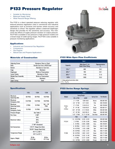 P133 Pressure Regulator
12 Pages
 P140 Pressure Regulator
4 Pages
 P303 Pressure Regulator
11 Pages
 P300 Pressure Regulator
11 Pages
 P203 Pressure Reducing Regulator
18 Pages
 F300 Pressure Regulator
7 Pages
 P600 Pressure Regulator
7 Pages
 P289RC Exhaust Booster
2 Pages
 W627 Liquid Gas Regulator
8 Pages
 F627 High Flow Gas Regulator
7 Pages
 BELLOFOAM™ 7804
1 Page
 BELLOFOAM™ 7704
1 Page
 BELLOFOAM™ 7604
1 Page
 Marsh Catalog
84 Pages
 P79 Air Relays
4 Pages
 Automated Timing & Controls
142 Pages
 Motor Protection
86 Pages
 Digital Controllers
30 Pages
 P630 High Flow Gas Regulator
12 Pages
 P39 Standard Gas Regulators
4 Pages
 P40 & P40 NACE Regulators
2 Pages
 P912 Pressure Regulator
2 Pages
 P119 Control Valve
4 Pages
 BelGAS Product Overview LT5040
12 Pages
 KING-GAGE Product Catalog
12 Pages
 BelGas P200 Pressure Regulator
18 Pages


Archived catalogs


- Valve
- Connector
- Manual valve
- Cylinder
- Temperature probe
- Electrical power supply connector
- On/off valve
- Angular encoder
- Incremental encoder
- Pressure gauge
- Pressure limiter
- Gas valve
- Profile
- Double-acting cylinder
- Level probe
- Single-stage pressure regulator
- Liquid level sensor
- Rectangular connector
- Pneumatic cylinder
- Incremental rotary encoder