
Catalog excerpts
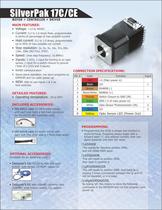
MOTOR + CONTROLLER + DRIVER SilverPak 17C/CE MAIN FEATURES: • Voltage: +12 to 40VDC • Current: 0.2 to 2.0 Amps Peak, programmable in terms of percentage of max possible current • Hold current: 0.2 to 1.0 Amps, programmable up to 50% of max possible run current • Step resolution: 2x, 4x, 8x, 16x, 32x, 64x, 128x, 256x (NO FULL STEP) • Speed: (max step frequency: 16.8MHz) • Inputs: 2 I/O’s, 1 input for homing to an opto sensor, 1 input for a switch closure to ground (Total of 2 I/O’s and 2 inputs) • RS485 communication • Stand alone operation, can store programs on EEPROM and run upon power up • NEW: Able to use inputs 1 & 2 as limit switches DETAILED FEATURES: • Operating temperature: -20 to 50°C • 090-00018 cable for motor comes with each unit (the other side is 4 flying lead wires) Included Accesories: • 090-00022 cable for DB-9 cable comes with each unit (with a red 4-pin connector for the RS232-485 converter card) • Designer’s kit: RS232-to-485 with push button, opto sensor, CD-ROM, cables (2) • Designer’s kit with USB485 converter card (USB485, push button, switch, CD, cables) Optional Accesories: (Available for an additional cost) PROGRAMMING: • Programming the R256 is simple and intuitive in HyperTerminal. Programs always begin with a forward slash “/”, and address number, then one alpha character and then the value: /1A5000R This stands for Absolute position 5000, and will rotate 5000 steps /1A5000A0R This will rotate to position 5000, then back to position 0 /1gA5000A0G5R This will rotate to position 5000, then back to 0, looping 5 times (commands between the ‘g’ and ‘G’ will be repeated, or in a loop) /1s0gA5000A0G5R By typing ‘s0’, this means to store the following commands in the EEPROM and run this program upon power up. Pin # Color Function Input 1 Red +V (Main power in) 2 Black I/O 1 3 Brown RS485B (-) 4 Black/White RS485A (+) 5 Orange Switch Closure to GND (IN) 4 6 Green GND (-V of main power in) 7 White Opto Sensor Phototransistor (IN) 3 8 Blue I/O 2 9 Yellow Opto Sensor LED (Power Out) CONNECTION SPECIFICATIONS:
Open the catalog to page 1
COMMON TECH SUPPORT QUESTIONS / RMA ISSUES: • MOTORS ARE HOT: Check holding current or running current. It could be too high. • POWER SUPPLY IS DRAWING EXCESSIVE CURRENT: Ensure polarity is not switched on the main power supply, or on the converter card if using the RS232 to RS485 converter. • MOTOR ROTATES, BUT IRRATICALLY, NOT SMOOTHLY: If one of the two drivers are blown, then only half of the driver works. If this is the case, turning on and off the pulses to move and stop the motor might cause the motor to rotate CW and CCW at random times, when it should only rotate in one direction....
Open the catalog to page 2All Lin Engineering catalogs and technical brochures
-
 SilverPak 17D Plus
1 Pages
-
 IP65 & IPX7 Vacuum Motors
1 Pages
-
 5818 ?Super Torque
1 Pages
-
 4518 ? Signature Series
1 Pages
-
 208 ? Standard Motor
1 Pages
-
 High Torque
1 Pages
-
 Why Lin 2014
2 Pages
-
 MICROSTEPPING DRIVER
2 Pages
-
 R208
R2083 Pages
-
 8718 HIGH TORQUE MOTOR
1 Pages
-
 8618 STANDARD MOTOR
1 Pages
-
 5718 HIGH TORQUE MOTOR
1 Pages
-
 5618 STANDARD MOTOR
1 Pages
-
 5609 STANDARD MOTOR
1 Pages
-
 5704 HIGH ACCURACY MOTOR
1 Pages
-
 4418 XTREME TORQUE MOTOR
1 Pages
-
 4118 SUPER TORQUE MOTOR
1 Pages
-
 4018 STANDARD MOTOR
1 Pages
-
 4209 HIGH TORQUE MOTOR
1 Pages
-
 4109 GOLD LINE MOTOR
1 Pages
-
 3518 STANDARD MOTOR
1 Pages
-
 3809 SERIES MODULAR MOTOR
1 Pages
-
 211 COMPACT MOTOR
1 Pages
-
 208 COMPACT MOTOR
1 Pages
-
 SILVERPAK 23D/DE
3 Pages
-
 SilverPak 23C
2 Pages
-
 GOLD LINE MOTOR
2 Pages
-
 MODULAR MOTOR 3609 SERIES
2 Pages
-
 1.8° SIZE 11
2 Pages
-
 STANDARD MOTOR
2 Pages
-
 SilverPak 17T
3 Pages
-
 1.8º SIZE 14
2 Pages
-
 HIGH TORQUE MOTOR 3509V
2 Pages
-
 Lin Catalog 2006
100 Pages


Archived catalogs
-
 SUPER TORQUE MOTOR 4118
2 Pages
-
 STANDARD MOTOR 5609
2 Pages
-
 STANDARD MOTOR 4018
2 Pages
-
 STANDARD MOTOR 8618
2 Pages
-
 SUPER TORQUE MOTOR 4118
2 Pages
-
 HIGH TORQUE MOTOR 4209
2 Pages
