- Catalogs
- LASER COMPONENTS
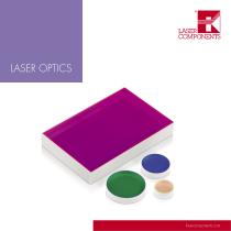
- Laser Optics
Laser Optics
1 /88Pages

Laser Optics
1 /88Pages
Catalog excerpts
LASER COMPONENTS
Open the catalog to page 1
small components
Open the catalog to page 3
Laser Optics Tradition Dear Reader, Thank you for your interest in LASER COMPONENTS’ products and services. In this catalog, we will provide you with a current overview of our wide range of laser optics. LASER COMPONENTS GmbH was originally founded as a sales company. Just four years later - in 1986 - the first production facility was opened for the coating of laser optics. Based on this experience, we have always been able Patrick Paul to follow our guiding principle: delivery of the highest quality. The positive f eedback from our customers and long-term sales success confirm this. In the spring...
Open the catalog to page 7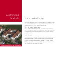
Customized Products How to Use this Catalog This catalog shall give an idea to our customers about our capabilities on laser optic production. We produce most components to custom specifications and delivery schedules, this is not a catalog of standard parts. One of Our Strengths: Custom Products One of LASER COMPONENTS’ strengths is the production of custom optics, even in small quantities. Simply provide us with your desired specifications such as material, size, shape, and coating and our product engineers will assess production feasibility. Further Information For many coatings in this catalog,...
Open the catalog to page 8
Germany / Worldwide LASER COMPONENTS GmbH Werner-von-Siemens-Str. 15 82140 Olching / Germany Nordic Countries LASER COMPONENTS Nordic AB Skars led 3 41263 Goteborg / Sweden France LASER COMPONENTS S.A.S. 45 Bis Route des Gardes 92190 Meudon / France Tel.: +33 1 3959 5225 [email protected] www.lasercomponents.fr USA LASER COMPONENTS USA, Inc. 116 South River Road Bedford, NH 03110 / USA Tel: +1 603 821 7040 [email protected] www.laser-components.com Great Britain LASER COMPONENTS (UK) Ltd. Goldlay House 114 Parkway Chelmsford Essex CM2 7PR / UK Tel: +44 1245 491 499 [email protected]...
Open the catalog to page 9
Coating Methods E-Beam Coating The e-beam process is the most widespread coating technique in laser technology and has been used at LASER COMPONENTS in its almost original form since 1986. In this method, dielectric coating materials are reactively evaporated in a high vacuum with an electron beam (e-beam), by injecting oxygen into the coating chamber. However, to deposit stable layers, the substrates must also be heated to approx. 250 °C. Our empirical evaluation has shown that evaporation geometry can be used in an e-beam chamber in such a way that different layer thicknesses can be deposited...
Open the catalog to page 10
Substrate Holder Rotation Axis Several Holder Planetary Rotation Vaccuum Chamber Heater, up to 300 °C Coating Material Electron Beam Source Evaporation Source Chamber Specifications Electron Beam Coating Chamber ▪▪ Maximum substrate diameter: 200 mm ▪▪ Typical batch size: 100 substrates at Ø = 1.0” ▪▪ Short coating times at temperatures above 250 °C ▪▪ Maximum flexibility: Simultaneous production of optics for different angles of incidence Features In this method, the deposition of different materials makes it possible to manufacture so-called cw/fs coatings in addition to high-power coatings....
Open the catalog to page 11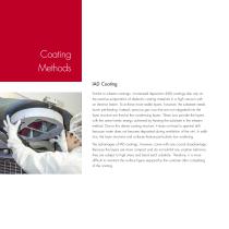
Coating Methods IAD Coating Similar to e-beam coatings, ion-assisted deposition (IAD) coatings also rely on the reactive evaporation of dielectric coating materials in a high vacuum with an electron beam. To achieve more stable layers, however, the substrate needs lower pre-heating. Instead, precious gas ions that are not integrated into the layer structure are fired at the condensing layers. These ions provide the layers with the same kinetic energy achieved by heating the substrate in the e-beam method. Due to this dense coating structure, it does not lead to spectral drift because water does...
Open the catalog to page 12
Several Holder Planetary Rotation Coating Vaccuum Chamber Material Heater, 80 – 150 °C Electron Beam Source Evaporation Source Ion Assisted Deposition Coating Chamber In the IAD method, the substrate surfaces are heated slightly to produce a uniform temperature at the surface. Due to melting of the coating material, which can reach up to 2000 °C substrates can themselves heat up to 150 °C depending on the coating design and material deposited. The ion sources operated at several kilowatts also produce radiation heat. Thus, substrates continue to heat up the longer they are in the coating chamber....
Open the catalog to page 13
Coating Methods IBS Coating Unlike e-beam and IAD coatings, the coating material in the ion beam sputtering (IBS) method is not evaporated by an electron beam but rather knocked out of a target by an ion beam and atomized (sputtered). Therefore, the material particles have particularly high kinetic energy and are very flexible when they deposit on the substrate. Thus, voids can be easily filled. This results in layers with very low scattering and particularly smooth surfaces. The layers are subject to even higher stress than in the IAD method. Compared to electron beam evaporation, the sputtering...
Open the catalog to page 14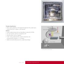
Chamber Specifications ▪▪ Batch capacity depends on the desired homogeneity of the coated optics (usually lower than in e-beam or IAD methods) Rotation Drive Substrates Holder Features Particle Flow ▪▪ Lowest scattering losses and very high reflection values (R > 99.99 %) Ion Source ▪▪ No water retention and thus no temperature drift ▪▪ Smooth surfaces with low roughness ▪▪ “Cold” coating method and thus suited for temperature and moisture-sensitive substrates, i.e. no heating ▪▪ Stable and reproducible process for complex layer designs Vaccuum Chamber Ion Beam Sputtering Coating Chamber
Open the catalog to page 15
Technology Layer Thickness and Materials Laser optic coatings consist of a series of single layers that have a layer thickness in the range of 10 – 100 nm. The layers must be absorption free from the UV to the near infrared range and have a suitable refractive index. Each layer design consists of two materials: one with a low refractive index and one with a higher refractive index. The same coating materials have been used for decades, irrespective of the technology applied. The material with the low refractive index used for all optics is SiO2. The high refractive material must be selected depending...
Open the catalog to page 16All LASER COMPONENTS catalogs and technical brochures
 FIBER OPTICS
112 Pages
 Components made for 3D LiDAR
8 Pages
 Infrared Components Catalog
136 Pages
 FLEXPOINT® Laser Modules
12 Pages
 APD Modules: A-Cube Series
8 Pages
 Company Profile and Products
48 Pages
 Laser Safety Eyewear
29 Pages


- Ethernet switch
- Industrial network switch
- Optical cable
- Infrared detector
- Pulsed laser
- Solid-state laser
- Glass lens element
- 5 ports network switch
- Coupler
- Precision laser
- Visible laser
- Optical prism
- Optical window
- Industrial laser
- Patch cable
- Fiber optics network switch
- Glass prism
- Optical detector
- Convex array lens element
- Laser lens element