Group: Tektronix

Catalog excerpts
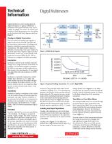
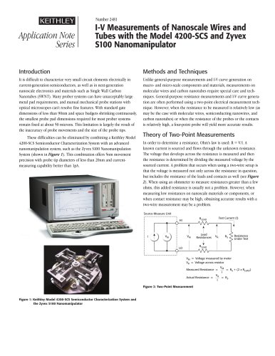
Analog to Digital Conversion The A/D converts the analog input signal to a digital output and is primarily responsible for key instrument characteristics of reading speed, linearity, resolution, normal mode rejection, and precision. The digital output is shown or obtained in several ways. One way is visually, via the front panel with a display of digits and other information. Another way is electronically, with results sent via a port (GPIB, RS-232, USB, or Ethernet) to a computer for further processing. Resolution Resolution is defined as the smallest detectable change on any range referenced to full scale. For example, if an instrument displays a maximum of 19,999 on any range, and the smallest detectable change in the input signal is ±1 least significant digit (LSD), then the resolution is 1/19999 or 0.005%. DIGITAL MULTIMETERS & SYSTEMS Resolution is commonly expressed as a whole number plus a fraction, e.g., 5½ digits. The whole number represents the number of digits that can display the numbers from 0 to 9. The fraction indicates that the most significant digit has one or more non-zero states, that is, it can display 0, 1, or 2. Sensitivity Sensitivity is similar to resolution in that it deals with the smallest change of the input signal the instrument can detect. However, sensitivity is not referenced to full scale, so it is expressed in absolute terms and applies to the lowest range on any function. The sensitivity of a 7½-digit DMM is 10nV if its lowest measurement range is 200mV. Accuracy Accuracy is specified as a two-term specification: ±(% of reading + % of range) or as (ppm of reading + ppm of range). The closer to zero on the range that the percent of range term of the specification is, the greater the weight it has in the accuracy calculation. The closer to full scale on the range the percent of reading term of the specification is, the greater the weight it has in the accuracy calculation. The best accuracy is obtained near full scale. Digital Display Precision Reference Ohms Converter Precision Shunts Digital Output Ports (IEEE-488, USB, RS-232, Ethernet) Figure 1: DMM Block Diagram Input as % of Full Scale 50% 100% Accuracy ±(0.1% + 1 count) Figure 2: Expected Reading Uncertainty: 5½- vs. 6½-Digit DMMs Accuracy is also generally stated under several conditions, including ±1°C, ±5°C operating temperature, and 24-hour, 90-day, and one-year calibration intervals. The expected accuracy can be improved by controlling temperature variations in the environment and by electing more frequent calibration intervals. Figure 2 illustrates the effect on accuracy at various levels of input signal within the measurement range. Accuracy for both meters is specified at ±(0.1% + 1 count). Loading and Input Impedance Loading is the disturbance to the circuit being measured caused by the finite input impedance of the DMM. Input impedance is the equivalent resistance and capacitance of the input terminals of the DMM. Loading error (Figure 3) is the difference between the voltage measured by the meter (V M ) and the voltage of an ideal source (VS ). Voltage burden error (Figure 4) is the difference between the expected current through the load (R L ) and the measured current (IM) caused by the finite voltage drop of the measuring instrument. Two-Wire vs. Four-Wire Ohms Two-terminal DMMs source test current through the measuring test leads, terminating at the HI-LO inputs of the DMM. This two-wire ohms system works fine for most resistance measurement applications. However, the I-R drop in the test leads (R L ) can cause inaccuracies that become apparent in lower resistance measurements (Figure 5). Four-wire ohms or Kelvin measurements bypass the voltage drop across R L by bringing two high impedance voltage sense leads out to the unknown R X. There is very little current in the sense circuit because of the high input impedance, so there's effectively no I-R drop in the leads, and the voltage seen by the sense Technical information: Digital multimeters Technical information: Digital multimeters Digital multimeters convert analog signals to digital information. In general, DMMs have a minimum of five typical functions. They are DC voltage, AC voltage, DC current, AC current, and resistance. While specifications vary, most DMMs can be described with block diagrams similar to Figure 1. Digital Multimeters Technical Information
Open the catalog to page 1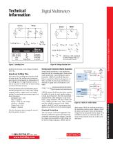
Technical Information Technical information: Digital multimeters Effect on Loading Error Increase Decrease Increase Increase Figure 3: Loading Error terminals is the same as the voltage developed across R X. Speed and Settling Time Every meter has a settling time associated with its input circuit. The reading rates or measurement speeds of instruments are independent of the settling times. For high resolution meters, it may be necessary to allow time for input settling to achieve full rated accuracy. Several parameters affect measurement speed, including integration rate (NPLC), filter...
Open the catalog to page 2All Keithley Instruments catalogs and technical brochures
-
 6220-6221
5 Pages
-
 6482
64823 Pages
-
 2520
25208 Pages
-
 2606B
2606B13 Pages
-
 2601B
2601B20 Pages
-
 AFG1000 Series
13 Pages
-
 AFG31000 Series Datasheet
22 Pages
-
 2182A Nanovoltmeter
6 Pages
-
 6 Series B MSO
69 Pages
-
 8 Series Sampling Oscilloscope
14 Pages
-
 8 Series Sampling Oscilloscope
14 Pages
-
 Isolated Measurement Systems
8 Pages
-
 TBS1000B-EDU Series
14 Pages
-
 3 Series MDO
36 Pages
-
 4 Series MSO
40 Pages
-
 TSG4100A Series
24 Pages
-
 2461-EC Graphical Potentiostat
16 Pages
-
 2460-EC Graphical Potentiostats
15 Pages
-
 2450-EC Graphical Potentiostat
15 Pages
-
 4200A-SCS Parameter Analyzer
45 Pages
-
 MDO4000C Series Datasheet
43 Pages
-
 RTPA2A
6 Pages
-
 TPA-N-PRE Datasheet
4 Pages
-
 DPO4PWR·MDO3PWR Datasheet
6 Pages
-
 DPO4LMT/MDO3LMT Datasheet
6 Pages
-
 DPO7000 Series Datasheet
28 Pages
-
 SourceXpress® Datasheet
4 Pages
-
 10G-KR Datasheet
8 Pages
-
 DPO70000SX Series Datasheet
46 Pages
-
 AWG4000 Series Datasheet
20 Pages
-
 TLA6400 Series Datasheet
14 Pages
-
 Potentiostats 2450-EC
8 Pages
-
 4200-SCS
16 Pages
-
 2013 Keithley product catalog
403 Pages
-
 Nanotechnology Measurement
13 Pages
-
 Semiconductor Device Test
11 Pages
-
 Series 2400 SourceMeter®Family
16 Pages


Archived catalogs
-
 Multimeter/Switch System
1 Pages