Group: Tektronix

Catalog excerpts

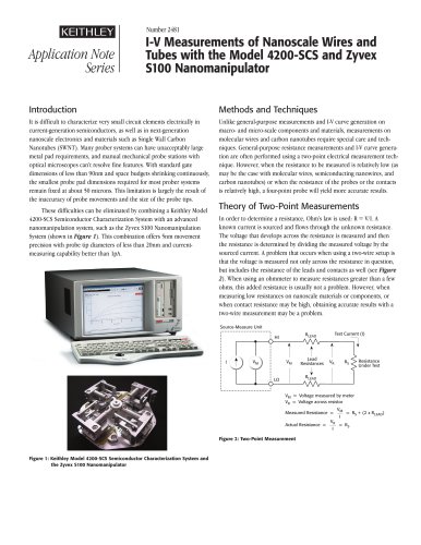
Digital Phosphor Oscilloscopes DPO7000 Series Datasheet Key features Ease of use features Pinpoint® Triggering provides the most flexible and highest performance triggering, with over 1400 combinations to address virtually any triggering situation Visual Trigger and Search precisely qualifies triggers and finds unique events in complex waveforms Advanced Search and Mark to find specific events in the entire waveform MyScope® custom control windows and right mouse click menus for exceptional efficiency 53 automated measurements, waveform histograms, and FFT analysis for simplified waveform analysis Tektronix understands that engineers rely on an oscilloscope throughout their design cycle, from prototype turn-on to production testing. The DPO7000 Series oscilloscopes' unique capabilities combined with exceptional signal acquisition performance and analysis accelerate your measurement tasks. TekVPI® Probe Interface supports active, differential, and current probes for automatic scaling and units 12.1 in. (307 mm) bright XGA display with touch screen Optional serial triggering and analysis Automated Serial Triggering, Decode, and Search Options for I2C, SPI, CAN, LIN, FlexRay, RS-232/422/485/UART, MIL-STD-1553, and USB 2.0 Automated Serial Analysis Options for MIPI® D-PHY DSI-1 and CSI-2, 8b/10b, Ethernet, and PCI Express Up to 40 GS/s real-time sample rate on one channel, up to 20 GS/s on two channels, and up to 10 GS/s on three or four channels Clock Recovery from serial data streams Up to 500 megapoint record length with MultiView Zoom™ >250,000 wfms/s maximum waveform capture rate with FastAcq® FastFrame™ segmented memory acquisition mode with >310,000 waveforms per second capture rate User-selectable bandwidth limit filters for better low-frequency measurement accuracy 64-bit NRZ Serial Pattern Trigger for isolation of pattern-dependent effects up to 1.25 Gb/s Optional technology specific analysis Software Solutions provide built-in domain expertise for MIPI® DPHY, Ethernet, BroadR-Reach, MOST, and USB 2.0 Compliance Testing, Jitter, Timing, Eye Diagrams, Power, DDR Memory Bus Analysis, and Wideband RF Limit and Mask Testing provide quick insight into signal characteristics Connectivity USB Host Ports on the front and side panels for quick and easy data storage, printing, and connecting USB peripherals Integrated 10/100/1000BASE-T Ethernet port for network connection and Video Out port to export the oscilloscope display to a monitor or projector Microsoft® Windows 7 64-bit operating system for easy connectivity and integration into your environment LXI Class C compliant
Open the catalog to page 1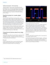
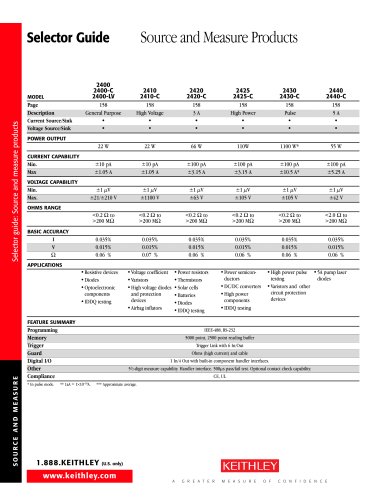
Datasheet TekScope Anywhere™ off-line analysis TekScope Anywhere™ brings the power of the oscilloscope analysis environment to the PC. Users now have the flexibility to perform analysis tasks including timing, eye, and jitter analysis outside the lab. Waveform data and setups 1 from Tektronix MDO3000, MDO4000, MSO/DPO5000, DPO7000C, or MSO/DPO70000C/D/DX/SX Series oscilloscopes can quickly be shared among team members and remote sites, resulting in improved efficiency. Simplified analysis for complex digital designs With the DPO7000C Digital Phosphor Oscilloscope Series, you can analyze...
Open the catalog to page 2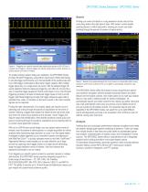
DPO7000C Series Datasheet - DPO7000C Series Search Finding your event of interest in a long waveform record can be time consuming without the right search tools. With today's record lengths pushing beyond a million data points, locating your event can mean scrolling through thousands of screens of signal activity. Capture – Triggering on a specific transmit data packet going across an RS-232 bus. A complete set of triggers, including triggers for specific serial packet content, ensures you quickly capture your event of interest. To enable complex system debug and validation, the DPO7000C...
Open the catalog to page 3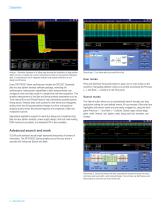
Analyze – Waveform histogram of a falling edge showing the distribution of edge position (jitter) over time. Included are numeric measurements made on the waveform histogram data. A comprehensive set of integrated analysis tools speeds verification of your design's performance. Search step 1: You define what you would like to find. Every DPO7000C Series oscilloscope includes the DPOJET Essentials jitter and eye pattern analysis software package, extending the oscilloscope's measurement capabilities to take measurements over contiguous clock and data cycles in a single-shot real-time...
Open the catalog to page 4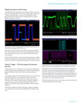
DPO7000C Series Datasheet - DPO7000C Series Digital phosphor technology The DPO7000C Series' digital phosphor technology provides you with fast insight into the real operation of your device. Its fast waveform capture rate – greater than 250,000 wfm/s – gives you a high probability of quickly seeing the infrequent problems common in digital systems: runt pulses, glitches, timing issues, and more. Customized serial triggering. Visual Trigger set to find a serial data pattern of 1101 0101. Digital phosphor technology enables greater than 250,000 wfm/s waveform capture rate and real-time color...
Open the catalog to page 5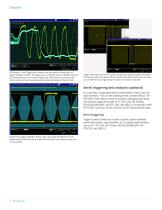
DDR memory. Visual Trigger used to isolate a rare occurrence of a write burst on a specific bit pattern in DDR3. The trigger event is a Write DQ burst of 11000000, when the DQ launch starts from a non-tri-state voltage value. DDR memory bus events involve clocks, strobes and data channels as well as multiple amplitudes and bursts of data. Trigger on the width of a burst of 10 pulses. By drawing a "Must be outside" area before the first clock pulse and a second "Must be outside" area after the tenth pulse, as shown, you can define a Visual Trigger setup that captures the desired burst width....
Open the catalog to page 6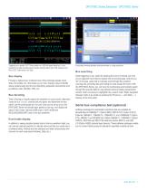
DPO7000C Series Datasheet - DPO7000C Series Triggering on a specific OUT Token packet on a USB full-speed serial bus. A bus waveform provides decoded packet content including Start, Sync, PID, Address, End Point, CRC, Data values, and Stop. Bus display Provides a higher-level, combined view of the individual signals (clock, data, chip enable, etc.) that make up your bus, making it easy to identify where packets begin and end and identifying subpacket components such as address, data, identifier, CRC, etc. Bus decoding Tired of having to visually inspect the waveform to count clocks,...
Open the catalog to page 7All Keithley Instruments catalogs and technical brochures
-
 6220-6221
5 Pages
-
 6482
64823 Pages
-
 2520
25208 Pages
-
 2606B
2606B13 Pages
-
 2601B
2601B20 Pages
-
 AFG1000 Series
13 Pages
-
 AFG31000 Series Datasheet
22 Pages
-
 2182A Nanovoltmeter
6 Pages
-
 6 Series B MSO
69 Pages
-
 8 Series Sampling Oscilloscope
14 Pages
-
 8 Series Sampling Oscilloscope
14 Pages
-
 Isolated Measurement Systems
8 Pages
-
 TBS1000B-EDU Series
14 Pages
-
 3 Series MDO
36 Pages
-
 4 Series MSO
40 Pages
-
 TSG4100A Series
24 Pages
-
 2461-EC Graphical Potentiostat
16 Pages
-
 2460-EC Graphical Potentiostats
15 Pages
-
 2450-EC Graphical Potentiostat
15 Pages
-
 4200A-SCS Parameter Analyzer
45 Pages
-
 MDO4000C Series Datasheet
43 Pages
-
 RTPA2A
6 Pages
-
 TPA-N-PRE Datasheet
4 Pages
-
 DPO4PWR·MDO3PWR Datasheet
6 Pages
-
 DPO4LMT/MDO3LMT Datasheet
6 Pages
-
 SourceXpress® Datasheet
4 Pages
-
 10G-KR Datasheet
8 Pages
-
 DPO70000SX Series Datasheet
46 Pages
-
 AWG4000 Series Datasheet
20 Pages
-
 TLA6400 Series Datasheet
14 Pages
-
 Potentiostats 2450-EC
8 Pages
-
 4200-SCS
16 Pages
-
 2013 Keithley product catalog
403 Pages
-
 Nanotechnology Measurement
13 Pages
-
 Semiconductor Device Test
11 Pages
-
 Series 2400 SourceMeter®Family
16 Pages


Archived catalogs
-
 Multimeter/Switch System
1 Pages