
Catalog excerpts

Performance data 3 Volumetric efficiency data 9 Crankcase flushing circuit and data 10 Functional symbols 11 Displacement control options 12 Shaft stress limits 13 Bearing life notes 14 Circuit and application notes 15 Motor operation at low temperature 17 Freewheeling notes 18 Installation data 19 Crankcase drain connections 20 HPC080 shaft options 21 HPC125 shaft options 22 HPC200 shaft options 23 HPC270/325 shaft options 24 HPC080 installation 25 HPC125 installation 27 HPC200 installation 29 HPC270 installation 31 HPC325 installation 33 Main port connections 35 Speed sensing options 36...
Open the catalog to page 2
Kawasaki StaffaӔ high torque, low speed radial piston motors use hydrostatic balancing techniques to achieve high efficiency, combined with good breakout torque and smooth running capability.The HPC series dual displacement models have two pre-set displacements which can be chosen from a wide range to suit specific application requirements. The displacements are hydraulically selected by a directional control valve which can be remote mounted or directly on the motor. Motor displacement can be changed with ease when the motor is running.These motors are also available in a continuously...
Open the catalog to page 3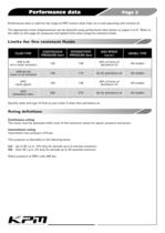
Performance data is valid for the range of HPC motors when fully run-in and operating with mineral oil. The appropriate motor displacements can be selected using performance data shown on pages 4 to 8. Refer to the table on this page for pressures and speed limits when using fire-resistant fluids. > FLUID TYPECONTINUOUSPRESSURE (bar)INTERMITTENTPRESSURE (bar)MAX SPEED(r.p.m.)MODEL TYPE HFA 5/95 oil-in-water emulsion13013850% of limits of petroleum oilAll modelsHFB 60/40 water-in-oil emulsion138172As for petroleum oilAll modelsHFCwater glycol10313850% of limits of petroleum oilAll...
Open the catalog to page 4
Consideration should be given to the required motor bearing life in terms of bearing service life. The factors that will determine bear life include: 1. Duty cycle - time spent on and off load 2. Speed 3. Differential pressure 4. Fluid viscosity, type, cleanliness and temperature 5. External radial shaft load 6. External axial shaft loadA heavy duty HP(HD)C motor can be ordered to further improve bearing life. Consult KPM for further details. >
Open the catalog to page 15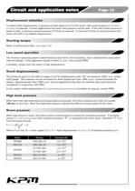
To select either displacement, a pressure at least equal to 2/3 of the motor inlet/outlet pressure (whicheveris higher) is required. In most applications the motor inlet pressure will be used. If the inlet/outlet pressure is below 3.5 bar, a minimum control pressure of 3.5 bar is required. In the event of loss of control pressure the motor will shift to its highest displacement. > Refer to performance data, (see pages 3-8). > The minimum operating speed is determined by load inertia, drive elasticity, motor displacement and system internal leakage. If the application speed is below 3...
Open the catalog to page 16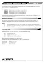
The flow rate of oil for the make-up system can be estimated from the crankcase leakage data (see pages 9) plus an allowance for changing displacement: e.g.HPC080 To change high to low in 0.25 sec requires 32 l.p.m. HPC125 To change high to low in 0.5 sec requires 15 l.p.m. HPC200 To change high to low in 0.5 sec requires 15 l.p.m. HPC270 To change high to low in 1 sec requires 24 l.p.m. HPC325 To change high to low in 1 sec requires 20 l.p.m.Allowances should be made for other systems losses and also for fair wear and tearӔ during the life of the motor, pump and system components. > The...
Open the catalog to page 17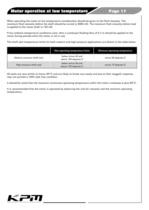
When operating the motor at low temperature consideration should be given to the fluid viscosity. The maximum fluid viscosity before the shaft should be turned is 2000 cSt. The maximum fluid viscosity before load is applied to the motor shaft is 150 cSt.If low ambient temperature conditions exist, then a crankcase flushing flow of 5 I/m should be applied to the motor during periods when the motor is not in use.The shaft seal temperature limits for both medium and high pressure applications are shown in the table below. All seals are very brittle at minus 40 > Non-operating temperature...
Open the catalog to page 18
All Staffa motors can be used in freewheeling applications. In all circumstances it is essential that the motor is unloaded (A and B ports connected together) and that the circuit is boosted.The required boost pressure will be dependent on speed and displacement. It should be noted that for Bђ series motors large flows will re-circulate around the motor. This will require a large re-circulating valve and consideration of circuit cooling as the motor will generate a braking torque. It is for these reasons that Cђ series motors are the preferred option for freewheeling applications. It is...
Open the catalog to page 19
Spigot Bolt torque The motor should be located by the mounting spigot on a flat, robust surface using correctly sized bolts. The diametrical clearance between the motor spigot and the mounting must not exceed 0.15mm. If the application incurs shock loading, frequent reversing or high speed running, then high tensile bolts should be used, including one fitted bolt. The recommended torque wrench setting for bolts is as follows: M18 312 +/_ 7 Nm 5/8 UNF 265 +/_ 14 Nm M20 407 +/_ 14 Nm 3/4Ԕ UNF 393 +/_ 14 Nm Shaft coupling Where the motor is solidly coupled to a shaft having independent...
Open the catalog to page 20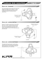
The recommended minimum pipe size for drain line lengths up to approx. 5m is 12.0mm 1/2 bore. Longer drain lines should have their bore size increased to keep the crankcase pressure within limits. Specify ԓV within the model code for extra drain port, G1/4Ԕ > (BSPF) . Connect this port into the main drain line downstream of a 0.35 bar check valve to ensure good bearing lubrication. The piping arrangement must not allow syphoning from the motorcase. The piping, from any drain port, must be taken above the level of the motorcase to ensure good bearing lubrication. The arrangement must not...
Open the catalog to page 21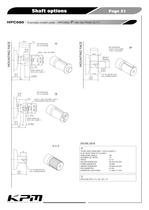
M20 x 1.0P x 50 LONG > 79.4 ؘ61.252 (DATUM) MOUNTING FACE MOUNTING FACE 10.3 6.410.9210.77 16583.581.9 > BASIC TAPER, ON DIA 0.1001/0.0999 : 1 72.0 269.6 135.6133.5 60.013ؘ59.99254.0053.95 KEY SUPPLIED-18.037/18.019 WIDE11.99/11.94 THICK 1/2"-20 UNF-2B X 32 FULL THREAD DEPTH 45 MIN. >
Open the catalog to page 22All Kawasaki Precision Machinery catalogs and technical brochures
-
 HPB Series
76 Pages
-
 M3X/M3B
35 Pages
-
 HPC Series
37 Pages
-
 HMC Series
43 Pages
-
 K3V/K5V/K7V
8 Pages
-
 HMB Series
92 Pages
-
 K3VL Series
76 Pages
-
 PV series
2 Pages
-
 ERU series
2 Pages
-
 HMF Series
72 Pages
-
 M7V / M7X Series
64 Pages
-
 HPC Series
37 Pages
-
 KPM-PV
2 Pages
-
 KDRDE KWE series
2 Pages
-
 KTEM/ KTMS series
2 Pages
-
 K3VL Series
72 Pages
-
 HMF Series
72 Pages
-
 KMP series
2 Pages
-
 ERU series
2 Pages
-
 K7VG
K7VG32 Pages
-
 K8V
K8V36 Pages
-
 K3VLS
K3VLS36 Pages
-
 KLSV 18
24 Pages
-
 KPES
KPES2 Pages
-
 HPC400
4 Pages
-
 hydraulic industriel vehicle
20 Pages
-
 B - Brake Valve
24 Pages
-
 M-Motor
35 Pages
-
 CBD - Counterbalance Valve
6 Pages
-
 M2X/M5X - Slewing motor
19 Pages
-
 Axial Piston Pump Series K3VG
34 Pages
-
 K3VG Series
34 Pages
-
 HMC-capability-brochure
6 Pages
-
 High-Power-HPC-Series-Datasheet
44 Pages


Archived catalogs
-
 HMB
HMB70 Pages
-
 HMC CATALOGUE
60 Pages
-
 Rotary Actuator HR Series
8 Pages
-
 B-motor-catalog-
70 Pages
-
 Datasheet - K3VL B Series
53 Pages
-
 THE K3VLB-SERIES
6 Pages
-
 Axial piston hydraulic motors
35 Pages


