Breakover Diodes
1 /8Pages

Breakover Diodes
1 /8Pages
Catalog excerpts
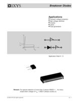
© 2000 IXYS All rights reserved H - 1 Breakover Diodes Applications Transient voltage protection High-voltage switches Crowbar Lasers Pulse generators i V VH VBO IH IBO Application Note H - 6 Remark: For special selection of more than 2 pieces IXBOD 1-... for every break down voltage of VBO > 2000 V please contact us.
Open the catalog to page 1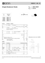
H - 2 © 2000 IXYS All rights reserved Symbol Conditions Ratings ID TVJ = 125°C; V = 0,8x VBO 20 µA VBO VBO(TVJ) = VBO, 25°C [1 + KT (TVJ - 25°C)] IRMS f = 50 HZ; Tamb = 50°C 1.4 A connection pins soldered to printed circuit (conductor 0,035x2mm) IAVM 0.9 A ISM tp = 0.1 ms; Tamb = 50°C non repetitive 200 A I²t tp = 0.1 ms; Tamb = 50°C 2 A2s Tamb -40...+125 °C Tstg -40...+125 °C TVJm 125 °C KT Temperatur coefficient of VBO 2·10-3 K-1 KP coefficient for energy per pulse EP (material constant) 700 K/Ws RthJA - natural convection 60 K/W - with air speed 2 m/s 45 K/W Weight 1 g Symbol Conditions Characteristic...
Open the catalog to page 2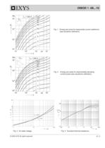
© 2000 IXYS All rights reserved H - 3 IXBOD 1 -06...10 Fig. 3 On-state voltage Fig. 4 Transient thermal resistance. Va = 0 m/s Va = 2 m/s Fig. 2 Energy per pulse for exponentially decaying current pulse (see waveforms definition). Fig. 1 Energy per pulse for trapezoidal current wafeforms (see waveform definition). t [s] TVJ = 125°C TVJ = 25°C iT [A] [V] VT [K/W] ZthJA
Open the catalog to page 3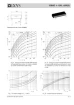
© 2000 IXYS All rights reserved H - 5 IXBOD 1 -12R...42R(D) Fig. 8 Transient thermal resistance. K A Dimensions in mm (1 mm = 0.0394") Fig. 5 Energy per pulse for single BOD element for trapezoidal wave current. EP must be multiplied by number of elements for total energy. Fig. 6 Energy per pulse for single BOD element for exponentially decaying current pulse. EP must be multiplied by number of elements for total energy. K A Va = 2 m/s n = number of BOD-Elements in series Va = 0 m/s [K/W] ZthJA t [s] Fig. 7 On-state voltage at TVJ = 125°C. [V] VT iT [A]
Open the catalog to page 5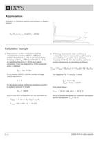
H - 6 © 2000 IXYS All rights reserved Application Protection of thyristors against overvoltages in forward direction. VD i BOD Thyristor VBO (TVJ) = VBO, 25°C [1+KT(TVJ - 25°C)] a. The maximum junction temperature shall be calculated for a module IXBOD 1 -30R at an ambient temperature Ta = 60 °C, an exponentially decaying current ITM = 40A, a pulsewidth tp = 2 ìs, an operating frequency f = 50 Hz and natural convection. From the diagram Fig. 6 the energy per pulse is obtained: Ep1 = 6 x 10⁻³ Ws For a module IXBOD1-30R the number of single IXBOD elements is: n = 3 At natural air cooling the thermal...
Open the catalog to page 6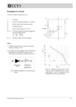
© 2000 IXYS All rights reserved H - 7 Notice 1. A IXBOD element has a maximum reverse blocking voltage of 10V. 2. For higher reverse voltages a fast, soft recovery diode must be connected in series (Fig. 9). This diode must fulfill the conditions of Fig. 10. T : Thyristor R1 : Current limiting resistance (0 - 200 Ù) D1 : Series-diode (fast recovery diode) D3 : Protection diode D4 : Zener diode, typical VZ : 3-6 V R2, C2 : Protection against parasitic triggering; recommended values: R2 : 100 - 1000 Ù C2 : 22 - 47 nF R3, C3 : Snubber network of the thyristor Example of a circuit A simple emergency...
Open the catalog to page 7
H - 8 © 2000 IXYS All rights reserved
Open the catalog to page 8All IXYS catalogs and technical brochures
 Polar3TM Power MOSFETs
2 Pages
 600V XPT IGBTs
2 Pages
 1200V XPT? IGBTs
2 Pages
 650V XPT? Trench IGBTs
2 Pages
 4500V POWER MOSFETs
2 Pages
 IXYS 2013
232 Pages
 BODO'S POWER SYSTEMS®
4 Pages
 IXYS News
6 Pages


Archived catalogs
 MICROCONTROLLERS Z8F0223QB005EG
245 Pages
 Selector guide
220 Pages
 IXYS RF Switch Mode MOSFET
2 Pages
 HiPerFETTM Power MOSFET
4 Pages
 NPT3 IGBT
4 Pages


- Technology switch
- Multipole switch
- Transistor module
- Touch switch
- MOSFET transistor
- Bipolar transistor
- Microcontroller
- Digital generator
- IGBT transistor
- Analog microcontroller
- General purpose microcontroller
- Sensitive switch
- Programmable microcontroller
- Radio-frequency switch
- Substrate
- ADC microcontroller
- Semiconductor switch
- Photovoltaic solar cell
- Delay generator