Catalog excerpts
Surge Protection Devices Low voltage Networks
Open the catalog to page 1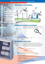
Direct impact on overhead High Voltage lines Direct impact on overhead Low Voltage lines Electromagnetic radiation on overhead lines Direct impact on external Lightning Protection System Rise of ground potential Electromagnetic radiation on lightning protection systems conductors Definition of transient overvoltages voltage Transient Overvoltages are defined as short duration and sharp increases in power line voltage. Large amplitude Transient Overvoltages Time Short duration in microseconds Standardized wave forms The standardized wave forms aim to represent transient overvoltages effects...
Open the catalog to page 2
Transient currents consequences for the equipment • Destruction (partial or complete) • Interference with normal operation • Premature ageing • Latent degradation Worsening factors > increasing number of sensitive equipment > electronic equipment increasing sensibility to transient currents > uninterruptible service requirement > costs of service interruption > standard requirements for SPD installation World lightning density map (Ng) Choosing Surge Protection Devices Building and power supply specifications Type1 surge arrester is mandatory. Type1 SPD technical characteristics...
Open the catalog to page 3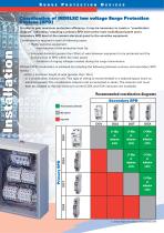
Coordination of INDELEC low voltage Surge Protection Devices (SPD) In order to gain maximum protection efficiency, it may be necessary to create a “coordination diagram” indicating / requiring a primary SPD level at the main switchboard panel and a secondary SPD level at the nearest electrical panel to the sensitive equipment. • Extended distance (greater than 30m) of wire between equipment to be protected and the primary level of SPD within the main panel: - limitation of ringing voltages created during the surge transmission. Efficient SPD coordination is achieved by including the...
Open the catalog to page 4
Surge Protection Device coordination Coordination by wiring P1 Primary SPD P2 Secondary SPD (close to the sensitive equipment) Coordination by inductor unit Inductor Surge Protection Devices: wiring Installation of primary SPD on busbars with associated short-circuit protection (fuses or circuit breakers) Installation of secondary SPD with associated short-circuit protection (fuses or circuit breakers).
Open the catalog to page 5
Surge protection Devices Low voltage surge protection devices and associated short circuit protection The following tests are required for these protective devices: • short-circuit current tests • overload current tests (industrial surges caused by switching power sources) Choosing short circuit protectors: The protective device must operate: The SPD associated with short circuit protection device must operate as fast as possible to interrupt fault conditions with appropriate current rating. The protective device must not operate: The short circuit protection device must not operate under...
Open the catalog to page 6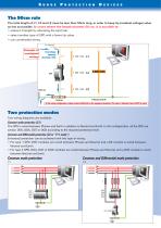
The 50cm rule The total length of L1, L2 and L3 must be less than 50cm long, in order to keep Up (residual voltage) value as low as possible. In cases where the length exceeds 50 cm, it is possible to: • reduce L3 length by relocating the earth bar; • select another type of SPD with a lower Up value; • use coordinated wiring. LV network Example of unadapted wiring: Overvoltage lightning discharge 10kA In this wiring configuration, voltage reaches 6800 Volts at the equipment terminals. This value is different from the SDP Up value. Two protection modes Two wiring diagrams are available:...
Open the catalog to page 7
Mountings according to different neutral systems Common and Differential Mode Protection (C2) Common Mode Protection (C1) Ivoi’Art - Lille - 03 28 52 67 54 - DOC045.VEN.01 Non contractual information - Printed with vegetable inks Indelec reserve the right to change data information without notice Wiring diagrams
Open the catalog to page 8All Indelec catalogs and technical brochures
-
 Prevectron3 Connect 2021
6 Pages
-
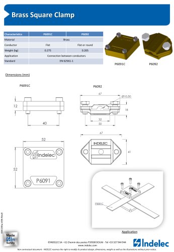 Brass Square Clamp
1 Pages
-
 TAPECONDUCTORS
1 Pages
-
 Test Clamp
1 Pages
-
 PREVECTRON® 3 S60
1 Pages
-
 Pivoting Saddle
1 Pages
-
 PREVECTRON 3® S60
1 Pages
-
 CORPORATE BROCHURE
12 Pages
-
 PREVECTRON 3 BROCHURE
2 Pages