- Catalogs
- KATO IMER S.p.A.
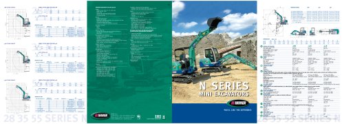
- CAT N Series
CAT N Series
1 /2Pages
CAT N Series
1 /2Pages
All KATO IMER S.p.A. catalogs and technical brochures
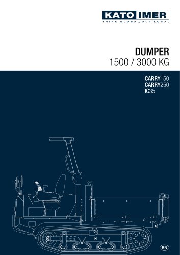 DUMPER 1500 / 3000 KG
16 Pages
 Silent hammer 55 / 570 kg
6 Pages
 MINIDUMPER 1500-2500 kg
12 Pages
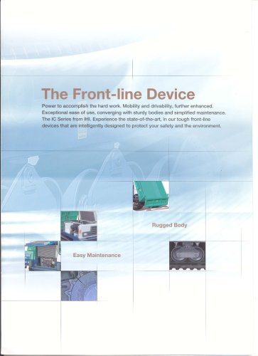 IC35 crawler carrier
3 Pages
 SILENT h AMMER 55-570 kg
6 Pages
 Dumper Ic 35
6 Pages
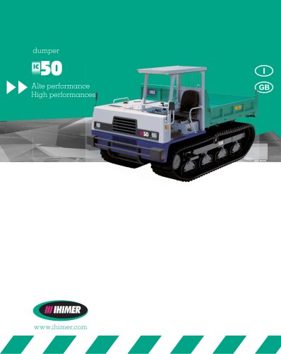 Dumper Ic 50
2 Pages
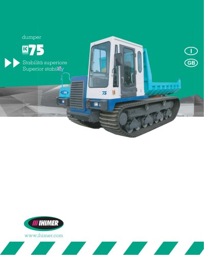 Dumper IC 75
2 Pages
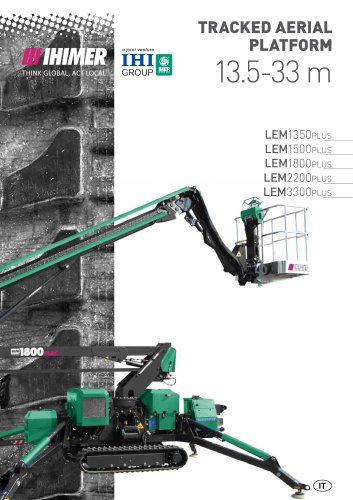
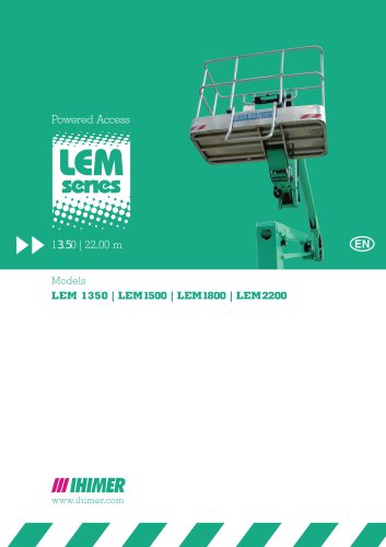 Lem series
26 Pages
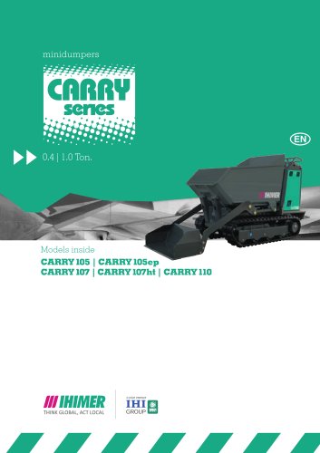 mini dumpers carry series
24 Pages
 Track loaders CL series
8 Pages
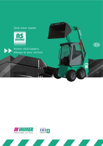 Skid-steer loader As series
12 Pages
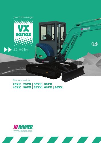 VX Series 2.0 - 8.0 Ton
32 Pages
 Full construction
8 Pages
Archived catalogs
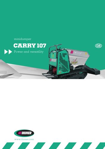 Carry 107
8 Pages
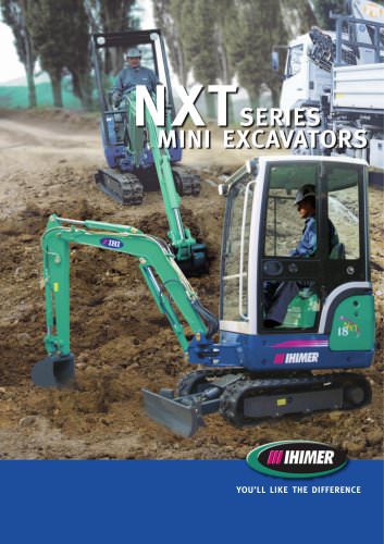 CAT NXT Series
6 Pages
Related Searches
- Boom excavator
- Diesel excavator
- Tracked excavator
- Construction boom excavator
- Medium boom excavator
- Mini-excavator
- Rock breaker
- Compact excavator
- Hydraulic rock breaker
- Excavator rock breaker
- Mini dumper
- Skid steer loader
- Breaker
- Combustion engine mini dumper
- Crawler mini dumper
- Carrier
- Front-loading mini dumper
- Hand-held breaker
- Compact mini dumper
- Vertical breaker
*Prices are pre-tax. They exclude delivery charges and customs duties and do not include additional charges for installation or activation options. Prices are indicative only and may vary by country, with changes to the cost of raw materials and exchange rates.