Complete Timer Catalog
1 /52Pages

Complete Timer Catalog
1 /52Pages
Catalog excerpts
Switching & Controls Switches & Pilot Lights Signaling Lights Relays & Sockets Circuit Breakers
Open the catalog to page 1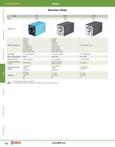
Selection Guide Switches & Pilot Lights Selection Guide Selection Guide Signaling Lights True Power OFF-delay Time Range Contact Configuration SPDT, DPDT SPDT, DPDT Repeat Accuracy Available Operating Voltage Timers ON-delay Interval OFF-delay One-shot Cycle (off first) Cycle (on first) Signal OFF delay Signal ON/OFF delay Contact Load Rating (resistive) Relays & Sockets ON-delay Interval OFF-delay One-shot Cycle (ON first) Cycle (OFF first) Signal OFF delay Signal ON/OFF delay Circuit Breakers Terminal Blocks 1. For Timing Diagrams Overview, see page 832. 2. For all series specific instructions,...
Open the catalog to page 2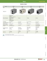
Selection Guide Switches & Pilot Lights Selection Guide Appearance Signaling Lights Time Range Contact Configuration SPDT, DPDT Relays & Sockets Sequential start ON-delay Recycler and instantaneous Recycler OFF start Recycler ON start Interval Interval ON delay Sequential interval Available Operating Voltage Repeat Accuracy Contact Load Rating (resistive) 1. For Timing Diagrams Overview, see page 832. 2. For all series specific instructions, accessories, and dimensions, see the individual series section. Contactors Terminal Blocks Circuit Breakers
Open the catalog to page 3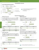
Timing Diagrams Overview Switches & Pilot Lights Timing Diagrams Overview Timing Diagrams Overview Guide to Reading Timing Function Diagrams Power Applied Start Input Terminals Shorted Start Input Terminals Opened Power Removed Timer Power 1. If power is disconnected during actual timing, most electronic timers reset to the preset time, ready for the re-application of supply voltage (except for GT3F “true power OFF Delay”). 2. NO = Normally open. 3. NC = Normally closed. Signaling Lights Input Signal NC Contact Opens Timer Begins Counting Relays & Sockets Timing Function Diagrams Overview ON-Delay...
Open the catalog to page 4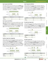
Timing Diagrams Overview Cycle 2 (signal start, OFF first) When voltage is applied to the coil, the contacts remain in the off state and the set time begins. At the end of the set time, the contacts transfer to the on state and remain in the on state until the set time elapses. The timer cycles between the two states until power is removed from the coil. Removing the coil voltage resets the timer. The set time for both the on state and the off state is the same. Applicable models: GT3A-1, -2, -3 and RTE-P(B)1. Voltage is applied to the coil at all times. When a start signal is supplied, the relay...
Open the catalog to page 5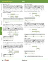
Signaling Lights Switches & Pilot Lights Timing Diagrams Overview Signal ON/OFF-Delay 1 Voltage is supplied to the coil at all times. When a maintained start signal is supplied, the contacts immediately transfer to the on state and the set time begins. When the set time has elapsed, the contacts transfer to the off state. The contacts remain in the off state until the start signal is removed. The contacts transfer back to the on state and remain in the on state for the set time. When the set time has elapsed, the contacts transfer to the off state and remain in the off state until the start signal...
Open the catalog to page 6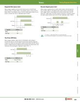
Timing Diagrams Overview Recycler Outputs (power start) When voltage is applied to the coil, both contacts remain in the OFF state and the set time, T1, begins. When T1 has elapsed, output 1 comes on and T2 begins. When T2 has elapsed, output 2 comes on. Both outputs remain on until power is removed from the coil. Applicable model: GT3W-A. When voltage is applied to the coil, both contacts remain in the off state and time T1 begins. When T1 has elapsed, both contacts transfer to the ON state and T2 begins. When T2 has elapsed, both contacts transfer back to the OFF state and T1 begins again....
Open the catalog to page 7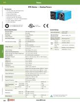
Signaling Lights Switches & Pilot Lights RTE Series — Analog Timers Key features: • 20 time ranges and 10 timing functions • Time delays up to 600 hours • Space-saving package • High repeat accuracy of ± 0.2% • ON and timing OUT LED indicators • Standard 8- or 11-pin and 11-blade termination • 2 form C delayed output contacts • 10A Contact Rating Cert. No. E9950913332316 (EMC, RTE) Cert. No. BL960813332355 (LVD, RTE) General Specifications Contact Ratings Solid state CMOS Circuit Operation Type Relays & Sockets Operation System Time Range Pollution Degree Over voltage category Contact Configuration...
Open the catalog to page 8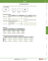
RTE Switches & Pilot Lights Part Numbering Guide RTE series part numbers are composed of 4 part number codes. When ordering a RTE series part, select one code from each category. Example: RTE-P1AF20 m Input Voltage Signaling Lights Part Numbers: RTE Series Description Part Number Code For internal circuits, see next page. Each function group has different timing functions. ON-delay, cycle OFF, cycle ON, signal ON/ OFF delay, OFF-delay, one-shot Relays & Sockets ON-delay, interval, cycle OFF, cycle ON Part Numbers Power Triggered 8-Pin Start Input Triggered Time Range Determined by Time Range...
Open the catalog to page 9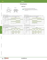
RTE Switches & Pilot Lights external control signal 4 Signaling Lights A: ON-Delay 1 (power start) Set timer for desired delay, apply power to coil. Contacts transfer after preset time has elapsed, and remain in transferred position until timer is reset. Reset occurs with removal of power. Item Delayed Contact Terminal Number Delayed Contact C: Cycle 1 (power start, OFF first) Set timer for desired delay, apply power to coil. First transfer of contacts occurs after preset delay has elapsed, after the next elapse of preset delay contacts return to original position. The timer now cycles between...
Open the catalog to page 10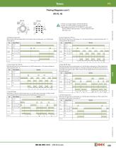
RTE Switches & Pilot Lights Timing Diagrams con’t RTE-P2, -B2 external control signal 4 RTE-B2 external control signal 1 Terminal Number 1. RTE-P2: Do not apply voltage to terminals #5, #6 & #7. 2. RTE-B2: Do not apply voltage to terminals #2, #5 & #8. 3. IDEC sockets are as follows: RTE-P2: SR3P-05* pin type socket, RTE-B2: SR3B-05* blade type socket, (*-may be followed by suffix letter A,B,C or U). A: ON-Delay 2 (signal start) When a preset time has elapsed after the start input turned on while power is on, the NO output contact goes on. Item B: Cycle 2 (signal start, OFF first) When the start...
Open the catalog to page 11All IDEC USA catalogs and technical brochures
 LD6A
LD6A8 Pages
 LF2B LED Illumination Units
6 Pages
 A series Switches & Pilot Lights
40 Pages
 BA Series Terminal Blocks
52 Pages
 EF1A Flameproof LED
24 Pages
 TWS series
40 Pages
 H6 Series
28 Pages
 Complete PLC Catalog
64 Pages
 Complete Terminal Blocks Catalog
22 Pages
 Complete Relay & Socket Catalog
76 Pages
 Complete Safety Overview
4 Pages
 Complete Power Supply Catalog
20 Pages
 Complete O/I Catalog
29 Pages
 All Product Brochure
6 Pages


Archived catalogs
 YC Series Contactors Catalog
24 Pages
 Lumifa LED Light Catalog
8 Pages
 All Product Brochure
2 Pages
 YS Series Contactors Catalog
60 Pages
 Complete Display Lights Catalog
44 Pages

- Power supply unit
- DC power supply
- AC/DC power supply
- Single-pole switch
- Push-button switch
- Technology switch
- Multipole switch
- DIN rail power supply
- Electromechanical switch
- DIN rail-mounted terminal block
- Rotary electric switch
- Rocker switch
- IP67 switch
- Illuminated push-button switch
- Signal tower light
- Touch push-button switch
- LED stack light
- Touch switch
- Action push-button switch