Complete Circuit Breakers Catalog
1 /12Pages

Complete Circuit Breakers Catalog
1 /12Pages
Catalog excerpts

Switching & Controls Switches & Pilot Lights Signaling Lights Relays & Sockets Contactors Terminal Blocks Circuit Breakers
Open the catalog to page 1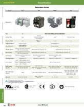
Circuit Breakers Selection Guide Signaling Lights Switches & Pilot Lights Selection Guide Series Page Relays & Sockets Visit www.IDEC.com/circuitbreaker Actuator Style Lever and Rocker (non-illuminated and illuminated) Slide switch, lever Hydraulic magnetic Electromagnetic trip Internal Circuits Series current trip Relay voltage trip Series current trip Auxiliary Contact Timers Protection Method Optional 125V AC 3A (resistive load), 30V DC 2A (resistive load) Alarm Contact Optional 125V AC 3A (resistive load). 30V DC 2A (resistive load) Inertial Delay Optional (for resistance to high inrush currents)...
Open the catalog to page 2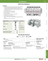
Circuit Breakers NC1V Switches & Pilot Lights NC1V Circuit Breakers Key features: Signaling Lights • Superior protection for a wide range of devices from sensitive electronic equipment to electrical control circuits. Applications include semiconductor manufacturing equipment, electronic controllers, computers, microprocessors, communications equipment, power supplies, machine tools, motors, and more. • Excellent tripping time curve performance • Flat retractable lever for safety operations • Slim housing design • Spring-up terminals allow for use of ring terminals • Fingersafe main circuit terminals...
Open the catalog to page 3
Circuit Breakers Switches & Pilot Lights Specifications Operator Style Retractable lever Internal Circuit Series trip (current trip), Relay trip (voltage trip) Protection Method Hydraulic magnetic tripping system, Magnetic tripping system (voltage trip) 2-pole Rated Short-circuit Capacity Signaling Lights Relays & Sockets Rated Current Time delay curve curve M (slow), curve A (medium), S (instantaneous) Only curves M and A are also available with inertial delay option. Rated Current Trip Voltage 24 to 48V DC (at 25°C) Voltage application duration 10 sec maximum, tripping time 0.1 sec maximum...
Open the catalog to page 4
Circuit Breakers Specify rated current, time delay curve, or voltage trip coil voltage in place of Internal Circuit Inertial Delay Auxiliary Contact Alarm Contact — One Auxiliary Contact and One Alarm Contact One Auxiliary Contact Two Auxiliary Contacts One Auxiliary Contact and One Alarm Contact Series Trip (Current Trip) Three Auxiliary Contacts NC1V-3113- 6 7 Two Auxiliary Contacts With Two Auxiliary Contacts and One Alarm Contact Terminal Blocks One Alarm Contact One Auxiliary Contact and One Alarm Contact Relay Trip (Voltage Trip) Two Auxiliary Contacts and One Alarm Contact M (slow)...
Open the catalog to page 5
Circuit Breakers Switches & Pilot Lights Internal Circuits 1-pole NC1V-1100 (Without auxiliary/alarm contacts) NC1V-1111 (With auxiliary contact) NC1V-1121 (With alarm contact) LINE Signaling Lights Relays & Sockets 2-pole NC1V-2100 (Without auxiliary/alarm contacts) LINE NC1V-2111 (With auxiliary contact) NC1V-2121 (With alarm contact) LINE One auxiliary contact. Also LINE One alarm contact. Also available available with two auxiliary contacts with one auxiliary contact and one alarm contact. 3-pole NC1V-3100 (Without auxiliary/alarm contacts) LINE NC1V-3111 (With auxiliary contact) NC1V-3121...
Open the catalog to page 6
Circuit Breakers Signaling Lights Switches & Pilot Lights Time Delay Curves at 40°C Current (percent load of the rated current) Relays & Sockets Current (percent load of the rated current) Note: The entire shaded area applies to AC. For DC, the shaded area on the right of the dashed line applies. Curve A (medium) With Inertial Delay Terminal Blocks Curve M (slow) With Inertial Delay Current (percent load of the rated current) Current (percent load of the rated current) Circuit Breakers Current (percent load of the rated current) Note: Inertial Delay option not available with S (instantaneous)...
Open the catalog to page 7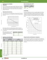
Circuit Breakers Switches & Pilot Lights NC1V Time Delay Curve and Ambient Temperature Relay Trip (Voltage Trip) at 25°C NC1V circuit breakers employ a hydraulic magnetic tripping system, where the rated current (trip current) is not affected by ambient temperatures. But the time delay may vary with the oil viscosity in the oil dash pot. Lower oil viscosity at higher temperatures results in a shorter delay, whereas at lower temperatures the delay will be longer. Inertial Delay Signaling Lights Temperature Correction Curve The time delay curves on the preceding page are measured at 40°C. With...
Open the catalog to page 8
Circuit Breakers NC1V Switches & Pilot Lights Dimensions (mm) 1-pole M4 Terminal Screw (up to 20A) M5 Terminal Screw (25A or more) 2-ø4.5 Holes (for screw mounting) M4 Terminal Screw (up to 20A) M5 Terminal Screw (25A or more) Signaling Lights Mounting Hole Layout (M4 Mounting Screws) Relays & Sockets 2-ø4.5 Holes (for screw mounting) Terminal Cover 2-ø4.5 Holes (for screw mounting) Terminal Cover Mounting Hole Layout (M4 Mounting Screws) 29.5 M4 Terminal Srew (up to 20A) M5 Terminal Screw (25A or more) Terminal Blocks 2-ø4.5 Holes (for screw mounting) Circuit Breakers
Open the catalog to page 9
Circuit Breakers M4 Terminal Srew (up to 20A) M5 Terminal Screw (25A or more) NC1V-2131 (one auxiliary contact and one alarm contact) NC1V-2112 (two auxiliary contacts) NC1V-2121 (one alarm contact) Signaling Lights Switches & Pilot Lights Mounting Hole Layout (M4 Mounting Screws) 29.5 2-ø4.5 Holes (for screw mounting) M3.5 Terminal Screw 2-ø4.5 Holes (for screw mounting) Relays & Sockets Terminal Cover M4 Terminal Screw (up to 20A) M5 Terminal Srew (25A or more) 2-ø4.5 Holes (for screw mounting) Circuit Breakers M4 Terminal Screw (up to 20A) M5 Terminal Srew (25A or more) NC1V-3131 (one auxiliary...
Open the catalog to page 10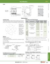
Circuit Breakers Mounting Hole Layout (M4 Mounting Screws) Switches & Pilot Lights 2-ø4.5 Holes (for screw mounting) Signaling Lights Terminal Cover Spring-up, fingersafe, slotted Phillips screw with square washer (up to 20A) Applicable Crimping Terminal R1.25-4 Spring-up fingersafe terminal (25A and 30A) (Minimum operating current) = (Rated current) × (Correction factor by installation angle) × (Reference minimum tripping current rate) Connectable Wire Size (mm2) Terminal Screw Auxiliary Contact Alarm Contact Voltage Coil Terminals Minimum operating current is calculated from the following formula:...
Open the catalog to page 11All IDEC USA catalogs and technical brochures
 LD6A
LD6A8 Pages
 LF2B LED Illumination Units
6 Pages
 A series Switches & Pilot Lights
40 Pages
 BA Series Terminal Blocks
52 Pages
 EF1A Flameproof LED
24 Pages
 TWS series
40 Pages
 H6 Series
28 Pages
 Complete PLC Catalog
64 Pages
 Complete Terminal Blocks Catalog
22 Pages
 Complete Timer Catalog
52 Pages
 Complete Relay & Socket Catalog
76 Pages
 Complete Safety Overview
4 Pages
 Complete Power Supply Catalog
20 Pages
 Complete O/I Catalog
29 Pages
 All Product Brochure
6 Pages


Archived catalogs
 YC Series Contactors Catalog
24 Pages
 Lumifa LED Light Catalog
8 Pages
 All Product Brochure
2 Pages
 YS Series Contactors Catalog
60 Pages
 Complete Display Lights Catalog
44 Pages

- DC power supply
- AC/DC power supply
- Single-pole switch
- Push-button switch
- Technology switch
- Multipole switch
- DIN rail power supply
- Electromechanical switch
- DIN rail-mounted terminal block
- Rotary electric switch
- Rocker switch
- IP67 switch
- Signal tower light
- Illuminated push-button switch
- Touch push-button switch
- LED stack light
- Touch switch
- Action push-button switch