iC-WD Switched-Mode Dual 5 V Regulator for 8 V to 36 V
1 /12Pages
iC-WD Switched-Mode Dual 5 V Regulator for 8 V to 36 V
1 /12Pages
Catalog excerpts
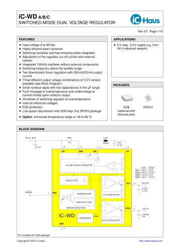
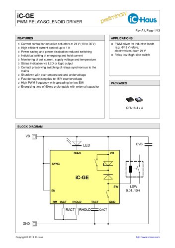
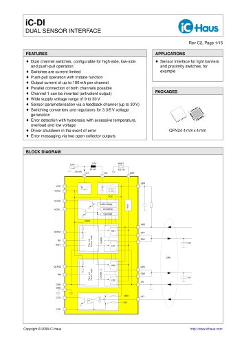
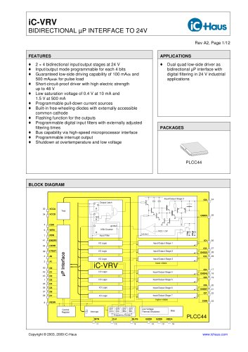
iC-WD A/B/C SWITCHED-MODE DUAL VOLTAGE REGULATOR Rev D1, Page 1/12 FEATURES © Input voltage 8 to 36 Vdc © Highly efficient down converter © Switching transistor and free-wheeling diode integrated © Adjustment of the regulator cut-off current with external resistor © Integrated 100 kHz oscillator without external components © Switching frequency above the audible range © Two downstream linear regulators with 200 mA/25mA output current © Three different output voltage combinations of 3.3V version available (see Block Diagram) © Small residual ripple with low capacitances in the ìF range © Fault message at overtemperature and undervoltage at current-limited open-collector output © Shutdown of switching regulator at overtemperature © Internal reference voltages © ESD protection © Low space requirement with SO8 resp. tiny DFN10 package © Option: enhanced temperature range of -40 to 85 °C APPLICATIONS © 5 V resp. 3.3V supply e.g. from 24 V industrial network PACKAGES SO8 (optional with thermal pad) DFN10 BLOCK DIAGRAM VB (8...36 V) ERROR (200 mA) RVB 1W 220mH LVH CVH 4.7mF 1mF CVCCA 4.7mF ERROR DETECTION iC-WD VREF VH SWITCHING CONVERTER OSCILLATOR TEMPERATURE UNDERVOLTAGE REFERENCE VCC REGULATOR VCCA REGULATOR 4.7mF WDC WDB WDA WD CVCC VCC +5 V +3.3 V +3.3 V +5 V VCCA +5 V +3.3 V +5 V +3.3 V 1 NER GND 4 VCCA 7 VCC 6 VH 5 VB 8 VBR 2 VHL 3 (25 mA) Pin numbers for SO8 package Copyright © 2007 iC-Haus http://www.ichaus.com
Open the catalog to page 1
iC-WD A/B/C SWITCHED-MODE DUAL VOLTAGE REGULATOR Rev D1, Page 2/12 DESCRIPTION The device iC-WD is a monolithic switching regulator with two downstream 5V resp. 3.3V linear regulators. In view of the high efficiency of the down converter for an input voltage range of 8 to 36 V, the iC-WD family is well-suited for industrial applications which require a stabilised 5 V resp. 3.3 V power supply with minimal power dissipation and few components. Switching transistor, free-wheeling diode and oscillator are integrated, limiting the necessary external elements for the switching regulator to the inductor,...
Open the catalog to page 2
iC-WD A/B/C SWITCHED-MODE DUAL VOLTAGE REGULATOR Rev D1, Page 3/12 ABSOLUTE MAXIMUM RATINGS Values beyond which damage may occur; device operation is not guaranteed. Item Symbol Parameter Conditions Unit No. Min. Max. G001 VB Supply Voltage -0.3 38 V G002 V(VBR) Voltage at VBR -0.3 38 V G003 I(VHL) Current in VHL Peak duration 50 ìs -800 800 mA G004 V(VH) Voltage at VH -0.3 8 V G005 I(VCC) Current in VCC -500 4 mA G006 I(VCCA) Current in VCCA -100 4 mA G007 V(NER) Voltage at NER -0.3 38 V G008 Vd() ESD Susceptibility at all pins HBM, 100 pF discharged through 1.5 k 2 kV WDB, WDC 1.5 kV G009 Tj...
Open the catalog to page 3
iC-WD A/B/C SWITCHED-MODE DUAL VOLTAGE REGULATOR Rev D1, Page 4/12 ELECTRICAL CHARACTERISTICS Operating Conditions: VB = 8...36V, LVH = 220 ìH, Ri(LVH) < 2 , CVH = 4.7 ìF, RVB = 1 , Tj = -40...125 °C, unless otherwise noted Item Symbol Parameter Conditions Unit No. Min. Typ. Max. Total Device 001 VB Permissible Supply Voltage Range 8 36 V Linear Regulator VCC (200 mA) 101 VCCnom Output Voltage I(VCC) = -200...0 mA; WD, WDC 4.75 5.00 5.25 V WDA, WDB 3.135 3.30 3.465 V 102 I(VCC) Permissible Load Current -200 0 mA 103 CVCC Min. Output Capacity for Stability 4.7 ìF 104 VCCrip Residual Ripple Evaluation...
Open the catalog to page 4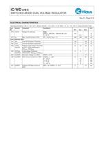
iC-WD A/B/C SWITCHED-MODE DUAL VOLTAGE REGULATOR Rev D1, Page 5/12 ELECTRICAL CHARACTERISTICS Operating Conditions: VB = 8...36V, LVH = 220 ìH, Ri(LVH) < 2 , CVH = 4.7 ìF, RVB = 1 , Tj = -40...125 °C, unless otherwise noted Item Symbol Parameter Conditions Unit No. Min. Typ. Max. 313 Vl(VH) Voltage VH with load WDA; I(VCC) + I(VCCA) = -200 mA, VB = 8 V 4.5 V Tj = 27 °C 5.0 V 314 Ioff Max. Cut-off Current in VHL VH < Vl(VH), RVB = 1 -500 -460 -400 mA Error Detection NER 401 Toff Thermal Shutdown Threshold 130 150 °C 402 Thys Thermal Shutdown Hysteresis 3 15 °C 403 VCC VCCA Relative Undervoltage...
Open the catalog to page 5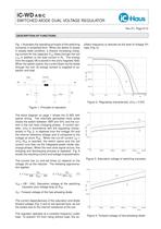
iC-WD A/B/C SWITCHED-MODE DUAL VOLTAGE REGULATOR Rev D1, Page 6/12 DESCRIPTION OF FUNCTIONS Fig. 1 illustrates the operating principle of the switching converter in simplified form. When the switch S closes in steady-state condition, a linearly increasing charging current for the capacitor CVH flows through the coil LVH in addition to the load current in RL. The energy from the supply VB is stored in the coil’s magnetic field. When the switch opens, the current flows via the diode through the coil; its energy content is supplied to capacitor and load. VB VH Vsat V(LVH) VD S LVH CVH RL Figure...
Open the catalog to page 6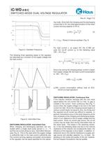
iC-WD A/B/C SWITCHED-MODE DUAL VOLTAGE REGULATOR Rev D1, Page 7/12 5.5V 6.0V 6.5V 7.0V 7.5V VH fosz 125kHz 100kHz 75kHz 25kHz 0 typ. 50kHz Figure 5: Oscillator Frequency The following three operating states of the regulator are described as a function of the supply voltage and the load current: Ioff 0 I(LVH) t T = 1/f VHL VH 0 VB r t f osz Figure 6: Intermittent flow SWITCHING REGULATOR: Intermittent flow When charging and discharging operation are concluded within a single clock pulse period (tr + tf < T) and the coil current drops to zero, intermittent flow prevails (Fig. 6). This is the case...
Open the catalog to page 7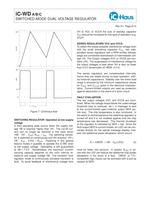
iC-WD A/B/C SWITCHED-MODE DUAL VOLTAGE REGULATOR Rev D1, Page 8/12 I(LVH) Ioff 0 t r VHL VB VH 0 T = 1/f osz Figure 7: Continous flow SWITCHING REGULATOR: Operation at low supply voltage A third operating state occurs when the supply voltage VB is scarcely higher than VH. The cut-off current can no longer be reached in this case since: (VB -VH -Vsat )/RLVH < Ioff . The switching transistor is switched on continuously and VH reaches: VH = VB - Vsat - I(VH) × RLVH. Factoring in this special feature makes it possible to operate the iC-WD even at low supply voltage. Operability is still guaranteed...
Open the catalog to page 8
iC-WD A/B/C SWITCHED-MODE DUAL VOLTAGE REGULATOR Rev D1, Page 9/12 APPLICATIONS INFORMATION DIMENSIONING The size of shunt RVB determines the cut-off current Ioff . By varying this in combination with the value for the inductor LVH, the power input, the efficiency and the timing can be adapted to the application. Normally the supply voltage range and the maximum output current for VCC and VCCA is specified. Define whether or not only intermittent flow is desired. The maximum inductance LVH can be estimated on the following basis: In the worst situation, charging and discharging process last exactly...
Open the catalog to page 9All IC-Haus catalogs and technical brochures
 Product Line Card
6 Pages
 iC-TL46 BLCC SD1C Blue LED
7 Pages
 iC212 HIGHSPEED PHOTORECEIVER
16 Pages
 Product overview
6 Pages


Archived catalogs
 iC-OV 5-Bit Optical Encoder
9 Pages
 Laser Webinar Handout
14 Pages
- Angular encoder
- Proximity switch
- Absolute rotary encoder
- Position transducer
- Multipole switch
- Photoelectric sensor
- Optical rotary encoder
- Transceiver module
- Linear position transmitter
- Magnetic rotary encoder
- Rectangular photoelectric sensor
- Flow sensor
- Linear encoder
- Touch switch
- Volume flow sensor
- Magnetic position sensor
- Signal conditioner
- Industrial switch
- Magnetic proximity sensor
- Metal position sensor