- Catalogs
- Hypro Pressure Cleaning
- Series 5300 OIPM
Series 5300 OIPM
1 /20Pages

Series 5300 OIPM
1 /20Pages
Catalog excerpts

Periodically inspect the pump and the systemcomponents. Perform routine maintenance as required (see Maintenance section). Օ Protect pump from freezing conditions by drainingliquid and pumping rust inhibiting solution, such as antifreeze, through the system, coating the pump interior. Use only pipe, hose and fittings rated for the maxi-mum (or greater) PSI rating of the pump. Օ Do not use these pumps for pumping water orother liquids for human or animal consumption. Donot exceedrecommended speed, pressureand temperature for pump and equipment being used. Օ Before servicing,disconnect all power,...
Open the catalog to page 2
(not longer) .Once again, a rust inhibitorshould be injected into the pump before both ports are plugged and the pump is stored. Then, plug both ports to keep out air until pump is used again. The pump should not be subjected to high suction line vacu-ums. To check on this, install a compound gauge at pump inlet. For ultimate performance and life, the vacuum should be limit- edto5inches of mercury. High vacuum conditions may cause premature product failure and void warranty. > Use a pressure regulator to limit incoming pressure to 20 psiwhen equipped with a suction side injector. Volume, pressure...
Open the catalog to page 4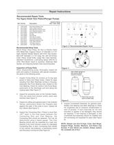
Used for SeriesRef.Part No.Description 532153245300 A1055-0005Seal Ring Seating ToolB3010-0052Valve Cage ExtractorՕՕ C3010-0061Main Bearing Support ToolՕ D3010-0063Cam Bearing Support ToolՕՕ E3010-0064Support Bars (Qnty 2)Օ F3010-0065Pry BarՕՕ G3010-0066Wire BrushՕ H3010-0067Wire Brush HolderՕՕ I3010-0071Valve Seat ExtractorՕ J3010-0222Seal Ring Seating ToolՕ K3020-00013/16" Allen WrenchՕ L3020-00031/8" Allen WrenchՕՕ M3020-00091/16" Allen WrenchՕ Figure 6 Recommended Repair Tools Recommended Shop Tools Bench Press, Arbor Press, Air Gun or Electric Hand Drill, Metal Pipe, Support Fixture, (3"...
Open the catalog to page 5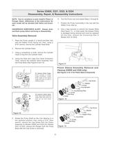
1 through 5 .7.Position the Pump horizontally in the vise with theSafety Cover side up.8.Use a claw hammer to remove the Grease fitting(See Figure 11). In most cases, the Grease Fitting isdamaged during removal and must be replaced [ > At this time, remove the Connecting Rod inModels 5321 & 5322 ]. NOTE: Due to variations in each model's Piston or Plunger Stack, differences in the instructions for each model will be denoted with italics and brack- ets.HAZARDOUS SUBSTANCE ALERT: Always drainand flush pump before servicing or disassembly. > 1.Place the Pump upright in a bench-mounted visewith the...
Open the catalog to page 6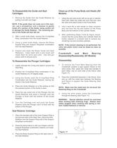
1.Remove the Guide from the Guide Retainer bypulling it out with one finger. 1.Using the port wire brush with an air gun or electrichand drill, clean the outlet port and inlet port, plus the valve and piston bores in the Pump Body.2.Use a hand file or belt sander to clean corrosionand rust from the top and bottom of the Pump Body and the bottoms of the cylinder Heads.3.After performing Steps NOTE: If the guide does not come out in this man-ner, use a screwdriver and a hammer to gently break off a section of the Guide, being careful not todamage the Guide Retainer. The remaining por- tion of the...
Open the catalog to page 8
1 through 3 ).6.Remove the Slinger Ring by working it off the Shaft. > 1.Install the back Main Bearing first. Place theBearing on the small opening end of the Main Bearing Support Tool with the Slinger Ring on top of the Bearing, and position it on the arbor press. WARNING: Special attention should be exercisedwhen working with retaining rings. Always wear safety goggles when working with spring or ten- sion-loaded fasteners or devices. 2.Place the Crankshaft in the Bearing and use thearbor press ram to press the Crankshaft through the Bearing until the Retaining Ring can be installed in the...
Open the catalog to page 9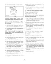
2 through 13 . > Metal ValveSeat Points up. NOTE: Make sure the Cam Bearing is in theupstroke position when installing the Cylinder Sleeves and Piston Assemblies. Figure 21 1.Place the assembled Guide Retainer Cartridge andPlunger into the plunger bore of the Pump body, making sure the Plunger and Connecting Rod seat together properly inside the Pump Body.2.Lubricate the O-ring and place it on top of the GuideRetainer Cartridge.3.Place the Seal Retainer Cartridge over the Plunger(beveled side down), and press it by hand into the Pump Plunger bore.4.Place a Washer on the Plunger Cap Screw, insert...
Open the catalog to page 10
THIS WARRANTYIS EXCLUSIVE. HYPRO MAKES NO OTHER WARRANTY, EXPRESS OR IMPLIED, INCLUD-ING BUT NOT LIMITED TO ANYWARRANTYOF MERCHANTABILITYOR FITNESS FOR APARTICULAR PUR- POSE. Hypros obligation under this warranty is, at HyproҒs option, to either repair or replace the product upon return of theentire product to the Hypro factory in accordance with the return procedures set forth below. THIS IS THE EXCLU-SIVE REMEDYFOR ANYBREACH OF WARRANTY.IN NO EVENT SHALLHYPRO BE LIABLE FOR ANYINCIDENTALOR CONSEQUENTIALDAMAGES OF ANYKIND, WHETHER FOR BREACH OF ANYWARRANTY, FOR NEGLIGENCE, ON THE BASIS OF STRICT...
Open the catalog to page 20All Hypro Pressure Cleaning catalogs and technical brochures
 PRODUCT CATALOG
236 Pages
 Transfer Pumps
7 Pages
 Gear Driven
3 Pages
 Centrifugal Pumps
41 Pages
 9302 Series
2 Pages

Archived catalogs
 DBS & DBA Diaphragm Pump OIPM
20 Pages
 Series 2100 Versa-Twin OIPM
16 Pages
 Hydraulic Pressure Washer OIPM
20 Pages
 Hydraulic Pump Selection Guide
38 Pages
 9302 Series Sales Sheet
2 Pages
 UAS Ceramic Nozzles
2 Pages
 HP Stainless Steel Nozzles
2 Pages
 TwinCap Sales Sheet
2 Pages
 ULD Sales Sheet
2 Pages
 ESI Sales Sheet
2 Pages
 2535S OIPM
12 Pages
 PowerLine Plunger OIPM
24 Pages
 Cleanload OIPM
12 Pages
 Foam Marker OIPM
20 Pages
 Series 5200 Piston Pump OIPM
8 Pages


